Table of Contents
Advertisement
Advertisement
Table of Contents

Related Manuals for AGCO GLEANER 3000


Summary of Contents for AGCO GLEANER 3000
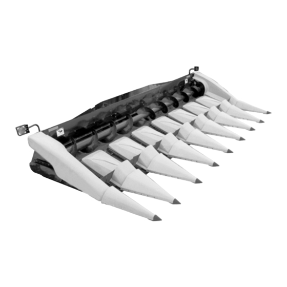
- Page 1 HEADER SERVICE MANUAL OPERATOR’S MANUAL GLEANER ® Model 3000 Corn Header F0204e73...
- Page 2 Find manuals at https://best-manuals.com...
- Page 3 CONTENTS GLEANER ® Model 3000 Corn Header 79023084 A Rev. CONTENTS GENERAL INFORMATION ..........................1-1 ADJUSTMENTS ..............................2-1 SERVICE GENERAL ............................3-1 SERVICE - FRAME GROUP ..........................4-1 SERVICE - ROW UNIT ............................5-1 79023084 A Rev. Find manuals at https://best-manuals.com...
- Page 4 CONTENTS 1-ii 79023084 A Rev. Find manuals at https://best-manuals.com...
-
Page 5: Table Of Contents
GENERAL INFORMATION GENERAL INFORMATION Contents GENERAL INFORMATION ..........................1-3 Safety Alert Symbol ........................... 1-3 Signal Words ............................. 1-3 Safety Precautions ............................ 1-4 Road and Highway Operation ........................1-6 Safety Decals, Lights, and Reflectors ....................... 1-7 Right and Left Hand ..........................1-12 Header Lift Cylinder Stop ........................ - Page 6 GENERAL INFORMATION 79023084 A Rev. Find manuals at https://best-manuals.com...
-
Page 7: General Information
GENERAL INFORMATION GENERAL INFORMATION Safety Alert Symbol FIG. 1: This is the safety alert symbol. It means ATTENTION! BECOME ALERT! YOUR SAFETY IS INVOLVED! Look for it, both in this manual and on safety signs on the machine. It will direct your attention to information that involves your safety and the safety of others. -
Page 8: Safety Precautions
GENERAL INFORMATION Safety Precautions FIG. 3: Read and understand this section of your service manual, the operator's manuals for the combine, and for all the attachments before operating the combine. Learn how to operate the combine and header and how to use the controls properly. - Page 9 GENERAL INFORMATION • FOR YOUR SAFETY and the safety of others, SAFETY AND OPERATIONAL DECALS that become damaged, faded, or come off should be replaced immediately. • REMEMBER that safe operation is no accident. • ALWAYS lower the Corn Head to the ground, or block, or lock it up securely before disconnecting or servicing any part of the system.
-
Page 10: Road And Highway Operation
GENERAL INFORMATION Road and Highway Operation FIG. 4: COMPLY with your state and local LAWS and REGULATIONS governing highway safety when moving machinery on a highway. • ALWAYS travel at a reasonable speed for road or field conditions. Whenever possible, avoid traveling near ditches, embankments and holes. -
Page 11: Safety Decals, Lights, And Reflectors
If they become damaged or lost, replace them immediately. They may be obtained from your local AGCO dealer. The part number and location on the combine or Corn Head are listed under each safety sign. - Page 12 GENERAL INFORMATION FIG. 6: Safety sign, 2. 71350365 FIG. 6 FIG. 7: Safety sign, 3. 71192887 FIG. 7 FIG. 8: Safety sign, 4. 70596071 FIG. 8 FIG. 9: Safety sign, 5. 71389339 FIG. 9 79023084 A Rev.
- Page 13 GENERAL INFORMATION FIG. 10: Safety sign, 6. 70591362a FIG. 10 FIG. 11: Safety sign, 7. 71359170 FIG. 11 FIG. 12: Safety sign, 8. 71359119 FIG. 12 79023084 A Rev.
- Page 14 GENERAL INFORMATION f0204e73 FIG. 13 FIG. 13: Safety sign locations. Corn Head Lights (A). Front & Rear Lens, Amber. FIG. 14: Reflector & Safety sign locations. f0204b30 FIG. 14 FIG. 15: Reflector locations. f0204b35 FIG. 15 1-10 79023084 A Rev.
- Page 15 GENERAL INFORMATION FIG. 16: Safety sign & reflector locations. 12-Row models only. f320001 FIG. 16 FIG. 17: Safety sign locations. F0204i07 FIG. 17 FIG. 18: Safety sign locations. f316002 FIG. 18 FIG. 19: Safety sign locations. WARNING: DO NOT operate the combine or Corn Head unless all shields are in place.
-
Page 16: Right And Left Hand
GENERAL INFORMATION Right and Left Hand FIG. 20: Throughout this manual when reference is made to Left Hand and Right Hand, it is determined by standing behind the machine and facing the direction of forward travel. e0830b15 FIG. 20 Header Lift Cylinder Stop FIGS. - Page 17 GENERAL INFORMATION FIG. 23: Engaged Lift Ram Stop: When the lift rams are fully extended the cylinder stop support hook can be released from the slot in the feeder housing side and pivoted downward until it fully contacts and surrounds three sides of the lift cylinder rod (2).
-
Page 18: Shields
GENERAL INFORMATION SHIELDS NOTE: Some pictures in this manual may show shields removed for visibility or access to parts of the header. Numerous shields must be opened and or removed to perform normal service and adjustment procedures. WARNING: NEVER operate the combine or allow others to operate it unless ALL SHIELDS supplied with the combine and its attachments are PROPERLY IN PLACE. - Page 19 GENERAL INFORMATION FIG. 25: For 4-Row and 6-Row Corn Heads, Right Hand feeder house countershaft shield (1) shown in the open position. To open, unlatch (2) and swing shield upward. To close, reverse the process. Raise drive shield (1) at rear of head before driving combine in for hooking up.
- Page 20 GENERAL INFORMATION FIGS. 27–30: Open Inner Gather Assembly: Raise Corn Head and set header lift cylinder stop. Reach under divider point, then pull pin (1) and lift gather assembly. Remove prop rod (2) from the prop rod keeper (4) and then remove quick pin (3) from storage hole (A).
- Page 21 GENERAL INFORMATION FIGS. 31–33: Open Inner Gather Assembly 12-Row 20 and 22 inch: Raise Corn Head and set header lift cylinder stop. Reach under divider point, pull quick pin (1), and then remove retaining pin (2). Raise divider and remove prop rod (3) from prop rod keeper (4).
- Page 22 GENERAL INFORMATION FIGS. 35–36: Close Inner Gather Assembly 12-Row 20 and 22 inch: Store the prop rod (1) in keeper (2) and lower gathering sheet. Lock gathering assembly in position by inserting retaining pin (3) and secure with quick pin (4). J801510 FIG.
- Page 23 GENERAL INFORMATION FIGS. 37–38–39–40: Open Outer Fenders: Reach under outer point, remove quick pin (6), and then remove pin (1) and lift fender assembly. Remove prop rod (2) from the prop rod keeper (4) and then remove quick pin (3) from storage hole (A). Use prop rod (2) to support fender assembly in mid mount bracket (5) and install quick pin (3).
- Page 24 GENERAL INFORMATION FIGS. 41–42: Open Outer Fenders 12-Row 20 and 22 inch: Reach under outer point and remove quick pin (1), retainer pin (2), and then lift fender assembly. NOTE: Unit may use a 7/16-14 X 4-1/2 inch capscrew with a center lock nut to retain front of gather sheet to cleavis arm (3).
-
Page 25: Attaching Corn Head To Combine
GENERAL INFORMATION Attaching Corn Head to Combine Combine Preparation FIG. 43: Refer to Combine Operator's Manual and adjust the combine for harvesting corn. • Operation Performance Tuning (Initial Combine Settings) Corn Harvesting Tips • Adjustments Feeder House Drum Height h710117 Concave FIG. - Page 26 GENERAL INFORMATION FIG. 45: For 4-Row and 6-Row header, lift up right hand hinged shield (1) before combine is driven into Corn Head c-2458 FIG. 45 FIG. 46: For 4-Row and 6-Row Corn Head, lower hinged flap (1) of right hand countershaft shield (2) after hook up is complete.
- Page 27 GENERAL INFORMATION FIG. 47: Rotate the feeder house latches back into the feeder house. Lower the feeder house. Line the left front corner of the feeder house with the left hand guide flange in the Corn Head opening and drive the combine squarely into the Corn Head.
- Page 28 GENERAL INFORMATION FIG. 49: Connect wiring harness to combine 13-pin plug (1). h828002 FIG. 49 Removing Header from Combine FIG. 50: Raise the Corn Head to full height and engage the header lift cylinder stop. DANGER: ALWAYS follow this procedure to engage the header lift cylinder stop.
- Page 29 GENERAL INFORMATION FIG. 52: For 4-Row and 6-Row header lift up right hand hinged shield (1). c-2458 FIG. 52 FIG. 53: Disconnect wiring harness from combine 13-pin plug (1) and plug connector into storage socket on corn head. h828002 FIG. 53 FIG.
-
Page 30: Leveling Header
GENERAL INFORMATION Leveling Header FIGS. 55–56: Without Lateral Tilt: The header is properly installed on the feeder house when the header is level with the ground. If the header does not appear level at first, make sure this is not caused by unequal tire pressure or the combine resting on uneven ground. - Page 31 This as a preview PDF file from best-manuals.com Download full PDF manual at best-manuals.com...
Need help?
Do you have a question about the GLEANER 3000 and is the answer not in the manual?
Questions and answers
2015 gleaner 3000 6 row 30 weight
The weight of a 2015 Gleaner 3000 6 row 30 is not provided in the context.
This answer is automatically generated