
Related Manuals for AGCO Glencoe CC4450


Summary of Contents for AGCO Glencoe CC4450
- Page 1 Glencoe ® CC4450 COMBINATION CHISEL PLOW (S/N 3676 & UP) OPERATOR’S MANUAL Form No. 1PD654399 April, 1999...
-
Page 3: Table Of Contents
Table of Contents INTRODUCTION DEALER/CUSTOMER INFORMATION TO THE DEALER:,TO THE CUSTOMER: ....2 SAFETY GENERAL OPERATION ......3 DECAL INFORMATION &... -
Page 5: Introduction
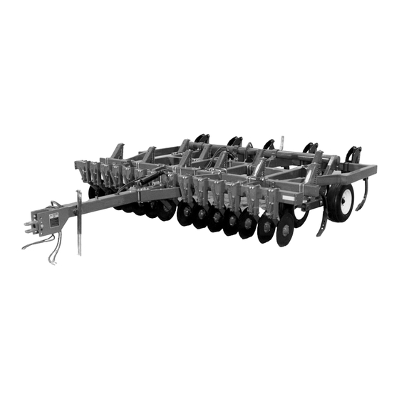
INTRODUCTION C445-1-1 C445-2-1 Fig. 1 - Rigid 15’ Model with Rippled Disc Cutters Fig. 2 - Folding 23’ Model with Concave Disc Cutters and Deep-Till Shanks The Model CC4450 Combination Chisel Plow is a highly versatile primary tillage tool, adaptable to spring or fall tillage operations. -
Page 6: Dealer/Customer Information
DEALER/CUSTOMER INFORMATION TO THE DEALER: TO THE CUSTOMER: Warranty Registration Warranty Registration A warranty registration form must be completed for Be sure to sign the registration form and keep your each serial-numbered unit by the dealer and signed copy. by both the dealer and the customer before or upon Know Your Equipment delivery. -
Page 7: General Operation
If there is any portion of this manual or of the machine’s operation you do not understand, contact your local authorized Glencoe® dealer, or AGCO® Corporation. · Always shut off tractor, shift to “Park” position (or shift to neutral), set brakes and cycle hydraulic levers before dismounting tractor or working around the machine. - Page 8 SAFETY PRECAUTIONS · Openings in the skin and minor cuts are · Raised wings can contact electric utility lines susceptible to infection from hydraulic fluid. If and overhead obstructions. Severe shock, injured by escaping fluid, see a doctor at once. injury, or death can result.
-
Page 9: Decal Information & Location
SAFETY DECALS DECAL LOCATION The following safety decals are installed to alert operators to hazards in specific machine areas. The decals are for personal safety. READ AND UNDERSTAND THE DECALS. · Keep decals clean by wiping off regularly. Use a cleaning solution if necessary. -
Page 10: Rockshaft Lockup Operation, Smv Sign
SAFETY ROCKSHAFT LOCKUP OPERATION To install lockup: 1. Raise implement to full height. 360459 2. Remove lockup from storage position and attach lockup to frame (Fig. 8). 3. Insert lockup pin and install clip pin. Attach lockup to rockshaft in storage position when not in use (Fig. -
Page 11: Operation
OPERATION TRACTOR PREPARATION CHISEL PLOW PREPARATION General General · Check fluid level in the tractor hydraulic system · Perform “Beginning of Day” maintenance as reservoir. Additional fluid may be required after outlined in the SERVICE Section. charging the chisel plow hydraulic circuits. ·... -
Page 12: Attaching To Tractor
OPERATION ATTACHING TO TRACTOR Hitch The implement is equipped with a combination clevis / tongue swivel hitch. For a tongue-type tractor drawbar, use the clevis hitch end. If the tractor has a clevis-type drawbar, use the tongue hitch end (Fig. 11). - Page 13 OPERATION ATTACHING TO TRACTOR Transport Safety Chain 1. Attach transport safety chain to chisel plow hitch with 1" x 8 " bolt furnished with machine bundle. Tighten bolt securely. 2. Attach chain clevis to tractor drawbar with bolt and locknut furnished in chain bundle. 3.
-
Page 14: Unhitching From Tractor
OPERATION UNHITCHING FROM TRACTOR WARNING! TO AVOID SERIOUS INJURY OR DEATH, STOP TRACTOR ENGINE, SHIFT TO PARK POSITION OR SHIFT TO NEUTRAL AND SET BRAKES 360459 BEFORE UNHITCHING. Chisel Lowered IMPORTANT! To prevent chisel point damage, do not lower chisel on concrete or rocks. 1. -
Page 15: Folding And Unfolding Wings
OPERATION FOLDING AND UNFOLDING WINGS To fold or unfold the wings on folding models, turn the selector valve to “WING FOLD” position. WARNING! TO AVOID SERIOUS INJURY OR DEATH, STOP TRACTOR ENGINE, DISENGAGE PTO, SHIFT TO PARK POSITION OR SHIFT TO NEUTRAL AND SET BRAKES BEFORE LEAVING TRACTOR. -
Page 16: Chisel Plowing
OPERATION CHISEL PLOWING DISC CUTTER OPERATION General General The chisel plow loosens the soil to the desired The disc cutters are used for cutting stalks and depth, allowing water penetration into the soil. residue. If stalk and residue cutting is not required, During the winter, the ground will freeze deeper and fully raise the disc frame and use the implement “weather out”... -
Page 17: Measuring Crop Residue
OPERATION MEASURING CROP RESIDUE Line-Transect Method Use the following procedure to determine the percentage of residue on the field. 1. Select a measuring tool: - 100’ tape - 100’ rope or string marked at 1’ intervals - 50’ tape - 50’ rope or string marked at 6" intervals 2. - Page 18 NOTES...
-
Page 19: Adjustments
ADJUSTMENTS LEVELING THE CHISEL PLOW All Models With the rockshaft lockup in storage position, drive the tractor forward and lower the implement into the ground. When the chisels are at the approximate desired depth, check that the frame is level and the chisels are at a uniform depth. -
Page 20: Gauge Wheels
ADJUSTMENTS GAUGE WHEELS Folding Models The gauge wheels provide implement stability for the larger models. With the implement fully lowered, position the wheels to just touch the ground: 1. Use gauge wheel adjustment lever (both sides, Fig. 26), to raise wheels same distance above ground level as desired chisel working depth. -
Page 21: Disc Cutters
ADJUSTMENTS DISC CUTTERS For optimum performance, each disc cutter should be in line with one of the shanks, except the center shank. If necessary, adjust the disc cutter spacing on the frame to obtain correct alignment. Disc cutter spring tension is increased or decreased by turning the adjuster nut at the top of each spring. - Page 22 Notes...
-
Page 23: Service
SERVICE GENERAL MAINTENANCE Beginning Of Day Beginning of Season · Perform daily lubrication. · Perform end-of-season lubrication. · Check and adjust tire pressure: · Check and adjust tire pressure. 9.5 L-15, 6-ply; 36 psi (250 kPa) · Tighten all loose bolts, U-bolts and L-bolts. ·... - Page 24 SERVICE LUBRICATION CHART Fig.* Item Grease 8 Hours 40 Hr. 200 Hr. Beginning End of Fittings (Daily) (Weekly) of Season Season Rockshaft Bearings 1 ea. Wheels 1 ea. Walking Beams 1 ea. Disc Cutter Pivots 1 ea. Disc Cutter Hubs 1 ea.
- Page 25 SERVICE GREASE FITTING LOCATIONS C445-6B-1 C445-21A-1 Fig. 31 - Rockshaft Fig. 33 - Walking Beams 1. Bearings 1. Beam Pivot C445-18A-1 C445-17B-1 Fig. 32 - Wheels Fig. 34 - Disc Cutters 1. Hubs 1. Bearing (behind disc)
-
Page 26: Troubleshooting
SERVICE TROUBLESHOOTING Problem Probable Cause Probable Correction Poor penetration Main frame not level Level frame Ground too hard Make multiple passes through field Wrong chisel tool point Select correct point Tires inflated unequally Inflate to correct pressure Malfunctioning depth control Repail cylinder or hydraulic system cylinder Worn points... -
Page 27: Bolt Torque Checking Intervals
SERVICE BOLT TORQUE CHECKING INTERVALS Disc Cutter and Spring Cushion Clamp C445-18B-1 C445-38A Fig. 35 - Disc Cutter Fig. 36 - Spring Cushion Clamp 1. Pivot Bolt 2. U-Bolts 1. Pivot Bolts 2. U-Bolts DISC CUTTER TORQUE First First First Beginning of Periodically CHECK... -
Page 28: Transport Lighting Wiring Diagram
SERVICE TRANSPORT LIGHTING WIRING DIAGRAM... -
Page 29: Special Torque Values
SERVICE SPECIAL TORQUE VALUES IMPORTANT! Over-tightening straight-thread hydraulic fittings damages sealing surfaces of JIC fittings and damages O-rings on adapter fittings. Note: Do not use pipe sealant or Teflon© tape on threads. JIC 37° Flare Adapter Fittings, Adapter-to-Tube " tube or hose: 12 ft-lb (16 N×m)* "... -
Page 30: Options
OPTIONS COULTER CUTTERS Cutters with 22" diameter concave discs are standard equipment. The discs cut aggressively and mix residue with worked soil. Rippled disc coulters 20" in diameter are available for loosely working the soil with minimal surface residue loss. Disc coulter down pressure is adjusted by tightening or loosening spring pressure. -
Page 31: Depth Control System, Shank Points, Shank Extensions
OPTIONS C445-50A C445-40A Fig. 40 - Depth Control System Console Fig. 41 - Points for Standard Shanks 1. Twisted, Right 2. Twisted, Left DEPTH CONTROL SYSTEM The DCS 3000 Depth Control System allows automatic or manual depth control (Fig. 40) of towed implements. -
Page 32: Specifications
SPECIFICATIONS RIGID and FOLDING MODELS FRAME LENGTH Basic Frame ........................90" (2286 mm) Basic Frame with Disc Cutters ...................114" ( 2896 mm) HITCH Type .......................Tongue / Clevis (Swivel) Length .........................119" (3023 mm) SHANK CLAMP TYPE Standard ........................Spring Cushion Deep-Till*..........................Auto Reset SHANK SIZE Standard ..................2"... - Page 33 SPECIFICATIONS RIGID MODELS Cutting Width Shanks Spacing Cutters Frame Width Transport Width Weight Drawbar Ft.(M) Total/Rear In. (mm) Ft. (M) Ft. (M) Hp.*** Required 7’0" (2.1) 7 / 3 12" (305 ) 6 9’6" (2.9) 9’8" (3.0) 3,111 8’7" (2.6) 7 / 3 15"...
- Page 37 Glencoe ® AGCO CORPORATION 4205 River Green Parkway Duluth, Georgia 30096 Printed in U.S.A.
Need help?
Do you have a question about the Glencoe CC4450 and is the answer not in the manual?
Questions and answers