Advertisement
VHX-73C-PU
Dakota Digital VHX Instrument Installation
For 1973 - '87 Chevy & GMC Pickups (Includes Heavy-Duty Trucks Through 1991)
1973 - '91 Chevy Blazer & GMC Jimmy
1973 - '91 Chevy & GMC Suburban
Your new VHX-73C-PU kit includes:
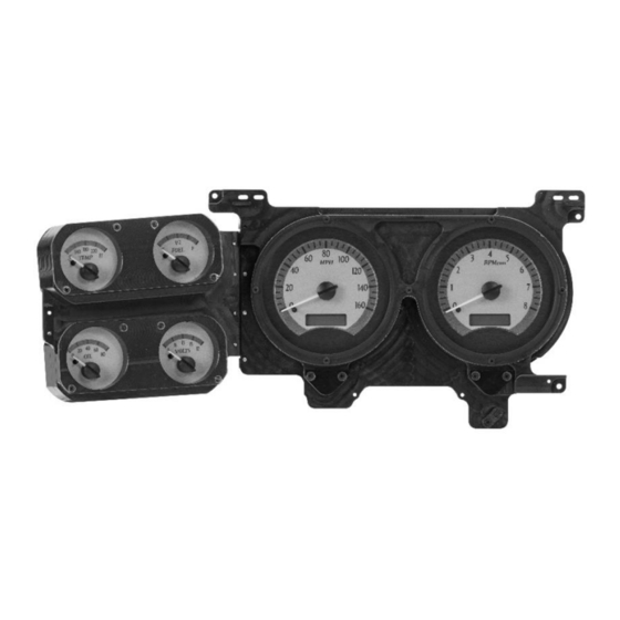
VHX Display
Universal
Installation Manuals
Sender Pack
(2) Turn Signal
Gear Indicator Lenses
Harnesses
(clear and blacked-out)
Mounting Tabs
Switch Assembly
CAT5 Cable
Control Box
" Pan
¾
" Flat Head
½
(4) 6-20 x
(2) 6-20 x
Head Screws
Screws
Manual # 650371E
Advertisement
Table of Contents

Related Manuals for Dakota Digital VHX-73C-PU


Summary of Contents for Dakota Digital VHX-73C-PU
- Page 1 Dakota Digital VHX Instrument Installation For 1973 - ‘87 Chevy & GMC Pickups (Includes Heavy-Duty Trucks Through 1991) 1973 - ’91 Chevy Blazer & GMC Jimmy 1973 - ’91 Chevy & GMC Suburban Your new VHX-73C-PU kit includes: VHX Display Universal Installation Manuals...
- Page 2 1. First, remove the 10 screws holding the bezel to the dash. Remove the stock instrument cluster, making sure to retain the four original instrument cluster screws for mounting the Dakota Digital VHX system later. 2. Fasten the three included mounting tabs to the VHX system.
- Page 3 4a. To optionally use the stock turn signal arrows, do not wire the turn signals to the VHX control box. Instead, use the two provided two-wire harnesses. The harnesses plug directly into connectors on the back side of your new VHX system. Connect the wires from these harnesses to your turn signal circuit and ground as shown below.
- Page 4 5. Carefully route the CAT5 cable through the dash to the control box mounting location and attach the VHX display to the dash using the four screws removed in Step One (see black arrows below). 5a. If using the stock automatic gear selector: glue the supplied clear lens over the gear selector opening in the bezel and mount the gear selector on the VHX dash using the two factory screws (white arrows in photo above).
- Page 5 6. Install the stock bezel over the VHX gauge cluster using the stock screws removed in Step One. Tighten the locations shown below (white arrows) first to ensure proper fitment and alignment; if the holes are not aligned correctly, Step Three may need to be repeated. 7.
Need help?
Do you have a question about the VHX-73C-PU and is the answer not in the manual?
Questions and answers