
Subscribe to Our Youtube Channel
Related Manuals for BEA LZR-H100


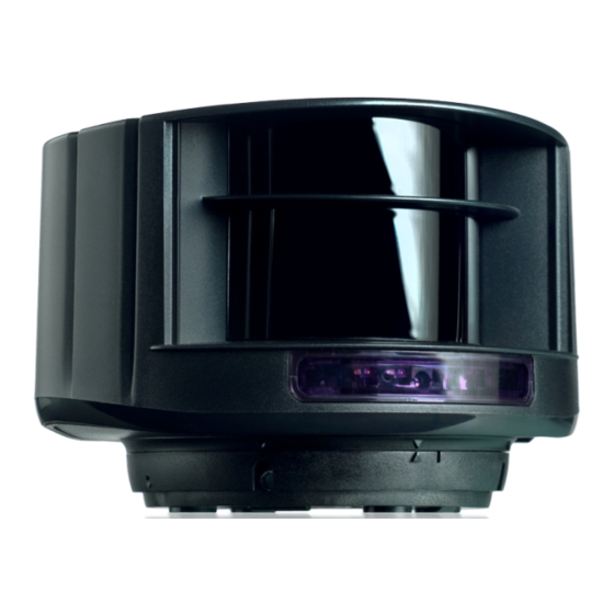
Summary of Contents for BEA LZR-H100
- Page 1 ® -H100 LASER SCANNER FOR BARRIERS & GATES with max. detection range of 32’ × 32’ User’s Guide Visit website for available languages of this document. 75.5984.03 LZR-H100 20191125 Page 1 of 16...
-
Page 2: Installation And Maintenance
This device is not intended for use in with any automatically activated doors. US Pat. No. 7,084,388, which is not owned by BEA, covers automatic doors comprising, among other things, a scanning detector. The LZR-H100 is not sold with consent, implied or otherwise, for use with automatically activated doors, as set forth in the aforementioned patent. -
Page 3: Led Signal
All 4 LEDs can be switched off and on again by remote control. This can be useful in cases where the sensor should not draw any attention. SYMBOLS Possible Remote control Caution! remote control sequence Laser radiation adjustments Factory values Alarm Quick installation 75.5984.03 LZR-H100 20191125 Page 3 of 16... -
Page 4: How To Use The Remote Control
30 minutes after last use, the sensor locks access to the remote control session. To regain access, cycle the power. The remote control session will then be accessible for another 30 minutes. 30’ Page 4 of 16 75.5984.03 LZR-H100 20191125... - Page 5 If the reference is farther away, adjust the detection field width to the width of the barrier. In order to maximize safety for mixed traffic (vehicles and trucks), an additional vertical detection zone is recommended (LZR-I30). 75.5984.03 LZR-H100 20191125 Page 5 of 16...
-
Page 6: Application Requirements
APPLICATION REQUIREMENTS These requirements ensure optimal safety of the barrier in order to protect against contact with the barrier. DOUBLE ACCESS LANE 90° 45° • 2 LZR-H100 • 2 references, 1 for each sensor 0° SINGLE ACCESS LANE 90° 45°... -
Page 7: Recommended Mounting
(B). The area around the barrier is not safe. d (in) (in) h (in) Ensure there are no obstructions in front of the Do not cover the front face of the sensor with sensor! glass or plastic. 75.5984.03 LZR-H100 20191125 Page 7 of 16... - Page 8 Learn Orange/Black (no polarity) No detection LED signal at power-on: Correct positioning is needed Safety and opening detection Power on without test signal: Connect blue/white and blue wires to test or power supply. Page 8 of 16 75.5984.03 LZR-H100 20191125...
-
Page 9: Field Positioning
Adjust the tilt angle of the detection - The beginning of the opening field should be field with the hex key if necessary. approximately 15 inches above the ground. To finish, lock the sensor position using a screwdriver. 75.5984.03 LZR-H100 20191125 Page 9 of 16... - Page 10 Select the correct mounting side with or without reference. For best detection performance, use the sensor with the reference point. WITH REFERENCE WITHOUT REFERENCE (RECOMMENDED) By default, the sensor automatically adjusts the width of the safety field based on the reference. Page 10 of 16 75.5984.03 LZR-H100 20191125...
- Page 11 The safety field is necessary for the correct functioning of the installation. If the safety field is badly adjusted, the manufacturer of the sensor cannot be held responsible for inappropriate functioning of the installation. Always verify the correct functioning of the safety field before leaving the premisses. 75.5984.03 LZR-H100 20191125 Page 11 of 16...
- Page 12 If the 1st red LED stays ON and no moving objects are in the detection field, reduce the opening field size or launch a new learn. Always launch a new learn after adjusting the field dimensions. Page 12 of 16 75.5984.03 LZR-H100 20191125...
- Page 13 OUTPUT CONFIGURATION RELAY 1 A – NO P – NC P – NC A – NO R1 R2 RELAY 2 P – NC A – NO P – NC A – NO FACTORY VALUE 75.5984.03 LZR-H100 20191125 Page 13 of 16...
- Page 14 IMMUNITY NOTE: Select "high" if fog is causing unwanted detections. standard high MAGIC WAND learn learn factory visible safety field opening field values laser beams Page 14 of 16 75.5984.03 LZR-H100 20191125...
-
Page 15: Troubleshooting
Cut and restore power supply. an incorrect code was used No code is required to unlock during the first minute after powering. Can’t find your answer? Visit www.beainc.com or scan QR code for Frequently Asked Questions! 75.5984.03 LZR-H100 20191125 Page 15 of 16... -
Page 16: Technical Specifications
BEA, Inc. does not guarantee any use of the sensor outside of its intended purpose. BEA, Inc. strongly recommends that installation and service technicians be AAADM-certifi ed for pedestrian doors, IDA-certifi ed for doors/gates, and factory-trained for the type of door/gate system.
Need help?
Do you have a question about the LZR-H100 and is the answer not in the manual?
Questions and answers