Advertisement
Quick Links
Maintenance / Trouble Shooting
This document has been prepared for the purpose of training. It is based on the
respective operation and maintenance manuals. Operation and maintenance must be
performed in accordance with the operating and maintenance manuals!
Siemens AG
Sector Industry, I&S IS ICS2 KHC
P.O.Box 3240
D-91050 Erlangen
E-Mail: ics2khc.industry@siemens.com
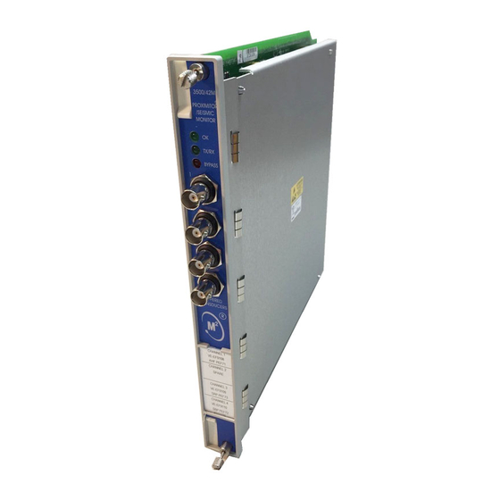
Bentley Nevada 3500, Proximitor
Advertisement
Troubleshooting

Related Manuals for Siemens Bently Nevada 3500 Proximitor


Summary of Contents for Siemens Bently Nevada 3500 Proximitor
- Page 1 This document has been prepared for the purpose of training. It is based on the respective operation and maintenance manuals. Operation and maintenance must be performed in accordance with the operating and maintenance manuals! Siemens AG Sector Industry, I&S IS ICS2 KHC P.O.Box 3240 D-91050 Erlangen E-Mail: ics2khc.industry@siemens.com...
-
Page 2: Changing Configuration
Section 3 — Common maintenance procedures Common maintenance procedures Once a 3500 Monitoring System is operating, it continuously measures and monitors a variety of supervisory parameters. The boards and components inside of 3500 modules cannot be repaired in the field and require no calibration. This section provides information for common tasks required under normal operating condititions. -
Page 3: Replacing Modules
3500 Monitoring System Installation and Operation Guide 4. Select the monitor channel to be adjusted in the Monitor Channel list box. 5. For all measurement parameters except phase, adjust the setpoint level by dragging the bar in the bar graph or by entering a value in the text box above or below the parameter. -
Page 4: Replacing An I/O Module
Section 3 — Common maintenance procedures 2. Remove the module to be replaced. Refer to Removing and inserting a main module on page 24. 3. Insert the new module Refer to Removing and inserting a main module on page 24. 4. - Page 5 3500 Monitoring System Installation and Operation Guide Check that the LEDs for the replaced module are indicating correct operation (see Reading the LEDs on page 16. The values of the measurement parameters of a channel are verified by using the Verification untility in the 3500 Rack Configuration program and the verification procedure in the reference manual for that module.
- Page 6 Section 3 — Common maintenance procedures 3.2.3.2 To install a spare full-height module 1. Ensure that the ejectors are in their normal position, flush with the front of the module. 2. Slide the main module into place, ensuring that they are properly in the guides provided on the floor and roof of the rack chassis.
- Page 7 3500 Monitoring System Installation and Operation Guide Verifying channels The boards and components inside of 3500 modules cannot be repaired in the field. Maintaining a 3500 rack consists of testing module channels to verify that they are operating correctly. Modules that are not operating correctly should be replaced with a spare.
- Page 8 Maintenance 3500/42 Operation and Maintenance Adjusting the Scale Factor and the Zero Position This section shows how to adjust the transducer scale factor and the transducer position, or "zero". The Scale Factor Adjustment can be used to accommodate any deviations in transducer scale factor as measured on the installed transducers.
- Page 9 3500/42 Operation and Maintenance Maintenance 6. Select the monitor you want to adjust. The Monitor screen will appear. 7. Select the Options button under the appropriate Channel. The configured Channel Options screen will appear. 8. Select the Customize button in the Transducer Selection box. A Transducer screen will appear.
- Page 10 Maintenance 3500/42 Operation and Maintenance Radial Vibration Ok Limits and Center Gap Voltage Transducer Upper Ok Limits Lower Ok Limits Center Gap Voltage w/ barrier w/ barrier w/ barrier barrier barrier(v) barrier (v) 3300 5mm -16.75 -16.75 -2.75 -2.75 -9.75 -9.75 3300 8mm -16.75...
- Page 11 3500/42 Operation and Maintenance Maintenance Thrust Position Ok Limits and Center Gap Voltage Upper Ok Limits Lower Ok Limits Center Gap Voltage Transducer w/ barrier w/ barrier w/ barrier barrier barrier barrier (V) 3300 5mm -19.04 -18.2 -1.28 -1.1 -10.16 -9.65 -1.28* -9.74*...
- Page 12 Maintenance 3500/42 Operation and Maintenance Differential Expansion Ok Limits and Center Gap Voltage Transducer Upper Ok Limits Lower Ok Limits Center Gap Voltage 25 mm -12.55 -1.35 -6.95 35 mm -12.55 -1.35 -6.95 50 mm -12.55 -1.35 -6.95 Eccentricity Ok Limits and Center Gap Voltage Transducer Upper Ok Limits Lower Ok Limits...
- Page 13 3500/42 Operation and Maintenance Maintenance Acceleration Ok Limits and Center Gap Voltage Transducer Upper Ok Limits Lower Ok Limits Center Gap Voltage w/ barrier w/ barrier w/ barrier barrier barrier barrier (V) 23733-03 -15.05 -13.85 -2.75 -3.10 -8.90 -8.475 -15.05* -2.75* -8.90* 24145-02...
- Page 14 Maintenance 3500/42 Operation and Maintenance When increasing or decreasing the zero position voltage, you are actually mapping the monitor full scale range to a portion of the transducer linear range. The zero position voltage adjustment range is dependent upon the full-scale range of the proportional value being adjusted, the transducer scale factor, and the transducer Ok limits.
- Page 15 3500/42 Operation and Maintenance Maintenance File menu. 5. Select the Options button on the 3500 System Configuration screen. 6. Select the monitor you want to adjust. The Monitor screen will appear. 7. Select the Options button under the appropriate Channel. The Channel Options screen will appear.
- Page 16 Gap (mm) 0.25 0.20 0.15 0.10 0.05 0.00 - 0.05 - 0.10 - 0.15 - 0.20 - 10 - 0.25 - 10 - 20 - 18 - 16 - 14 - 12 - 10 Gap (mils) 5 m System at 23 deg C (73 deg F) 5 m System at 0 deg C (32 deg F) 5 m System at 45 deg C (113 deg F) Figure 1 Typical 3300 XL 11 mm 5 m System Over Ambient Testing Range...
- Page 17 Troubleshooting 3500/42 Operation and Maintenance Troubleshooting This section describes how to troubleshoot a problem with the Proximitor®/Seismic Monitor or the I/O module by using the information provided by the self-test, the LED’s, the System Event List, and the Alarm Event List. Self-test To perform the Proximitor/Seismic Monitor self-test: 1.
- Page 18 3500/42 Operation and Maintenance Troubleshooting LED Fault Conditions The following table shows how to use the LED’s to diagnose and correct problems. OK Led TX/RX BYPASS Condition Solution 1 Hz 1 Hz Monitor is not Reconfigure the configured, is in Monitor, or exit Configuration Mode, or Configuration, or...
- Page 19 Troubleshooting 3500/42 Operation and Maintenance System Event List Messages This section describes the System Event List Messages that are entered by the Proximitor/Seismic Monitor and gives an example of one. Example of a System Event List Message: Sequence Event Event Class Event Event...
- Page 20 3500/42 Operation and Maintenance Troubleshooting The following System Event List Messages may be placed in the list by the Proximitor/Seismic Monitor and are listed in numerical order. If an event marked with a star (*) occurs the Proximitor/Seismic Monitor will stop alarming. If you are unable to solve any problems contact your nearest Bently Nevada Corporation office.
- Page 21 Troubleshooting 3500/42 Operation and Maintenance I/O Module Compatible Event Number: 63 Event Classification: Severe / Fatal Event Action: Verify that the type of I/O module installed matches what was selected in the software. If the correct I/O module is installed, there may be a fault with the Monitor Module or the Monitor I/O module.
- Page 22 3500/42 Operation and Maintenance Troubleshooting Pass Main Board +5V-B (Pass Main Board +5V - lower Power Supply) Event Number: 103 Event Classification: Potential Problem Action: Verify that noise from the power source is not causing the problem. If the problem is not caused by noise, check to see if one of the following components is faulty: - the Monitor Module - the Power Supply installed in the lower slot...
- Page 23 Troubleshooting 3500/42 Operation and Maintenance Fail Main Board +15V-B (Fail Main Board +15V - lower Power Supply) Event Number: 108 Event Classification: Potential Problem Action: Verify that noise from the power source is not causing the problem. If the problem is not caused by noise, check to see if one of the following components is faulty: - the Monitor Module - the Power Supply installed in the lower slot...
- Page 24 3500/42 Operation and Maintenance Troubleshooting Pass Main Board -24V-A (Pass Main Board -24V - upper Power Supply) Event Number: 113 Event Classification: Potential Problem Action: Verify that noise from the power source is not causing the problem. If the problem is not caused by noise, check to see if one of the following components is faulty: - the Monitor Module - the Power Supply installed in the upper slot...
- Page 25 Troubleshooting 3500/42 Operation and Maintenance * Configuration Failure Event Number: 301 Event Classification: Severe/Fatal Event Action: Download a new configuration to the Monitor Module. If the problem still exists replace the Monitor Module immediately. Monitor Module will stop alarming. Configuration Failure Event Number: 301 Event Classification: Potential Problem Action: Download a new configuration to the Monitor Module.
- Page 26 3500/42 Operation and Maintenance Troubleshooting * Module Removed from Rack Event Number: 325 Event Classification: Typical Logged Event Action: No action required. Monitor Module will stop alarming. Module Inserted in Rack Event Number: 326 Event Classification: Typical Logged Event Action: No action required. Device Events Lost Event Number: 355 Event Classification: Typical Logged Event...
- Page 27 Troubleshooting 3500/42 Operation and Maintenance Disabled Ch Bypass (Disabled Channel Bypass) Event Number: 417 Event Classification: Typical logged event Event Specific: Ch x Action: No action required. * Enabled Alert Bypass Event Number: 420 Event Classification: Typical logged event Event Specific: Ch x Action: No action required.
- Page 28 3500/42 Operation and Maintenance Troubleshooting * Enabled Mon Alarm Byp (Enabled Monitor Alarm Bypass) Event Number: 426 Event Classification: Typical logged event Action: No action required. Monitor Module will stop alarming. Disabled Mon Alarm Byp (Disabled Monitor Alarm Bypass) Event Number: 427 Event Classification: Typical logged event Action: No action required.
- Page 29 Troubleshooting 3500/42 Operation and Maintenance Switch To Backup Kph Event Number: 492 Event Classification: Potential Problem Event Specific: Ch pair x Action: Check to see if one of the following is faulty: - the primary Keyphasor transducer on the machine - the Monitor Module * Kph Lost Event Number: 493...
-
Page 30: Chapter 3 - Maintenance And Troubleshooting
Proximitor and Probes Chapter 3 — Maintenance and Troubleshooting Chapter 3 — Maintenance and Troubleshooting This section shows how to verify that the system is operating properly and identify parts of the system that are not working properly. The 3300 XL Transducer System (probe, cable and Proximitor® Sensor), when correctly installed and verified, does not need calibration or verification at regular intervals. - Page 31 3300 XL Proximity Transducer System Manual The scale factor verification uses the test setup as shown in the following figure: Multimeter Power Supply -24 Vdc 10 kΩ Proximitor® Sensor Probe, Target and Spindle Micrometer...
- Page 32 Chapter 3 — Maintenance and Troubleshooting Scale Factor Verification 500 µm 460 µm Multimeter -3.00 ± 0.1 Vdc 20 mil 18 mil 200 µm 500 µm 8 mil 20 mil 250 µm 10 mil Compensate for mechanical Compensate for mechanical Adjust gap to electrical zero by backlash and adjust the spindle backlash in the micrometer and...
-
Page 33: Troubleshooting
3300 XL Proximity Transducer System Manual If the incremental scale factor (ISF) or the average scale factor (ASF) of the system is out of tolerance, contact Bently Nevada Corporation for further information on possible calibration problems. The preceding pages indicate scale factor verification using a TK-3. This is suitable for rough verification. - Page 34 Chapter 3 — Maintenance and Troubleshooting The troubleshooting procedures use measured voltages as shown in the following figure and tables: XDCR Symbols for Measured Voltages Symbol Meaning Voltage measured between... Signal voltage from the OUT and COM transducer Power supply voltage Power Source and Common Supply voltage at and COM...
- Page 35 3300 XL Proximity Transducer System Manual Fault Type 1: V > -17.5 Vdc or V < -26 Vdc XDCR XDCR Possible causes: • Faulty power source • Faulty field wiring • Faulty Proximitor® Sensor Measure V Faulty Power Supply > -17.5 Vdc or V <...
- Page 36 Chapter 3 — Maintenance and Troubleshooting XDCR Measure V Faulty Field XDCR Wiring > -17.5 Vdc or V < -26 Vdc? XDCR XDCR Faulty Proximitor® Sensor Fault Type 2: V = 0 Vdc Possible causes: • Incorrect power source voltage •...
- Page 37 3300 XL Proximity Transducer System Manual Measure V Short in wiring or at Proximitor® = 0 Vdc? Sensor terminal connection Faulty Proximitor® Sensor...
- Page 38 Chapter 3 — Maintenance and Troubleshooting Fault Type 3: -1 Vdc < V < 0 Vdc Possible causes: • Probe is incorrectly gapped (too close to target) • Incorrect power source voltage • Faulty Proximitor® Sensor • Probe is detecting other material than target (counterbore or machine case) •...
- Page 39 3300 XL Proximity Transducer System Manual Faulty Measure V Proximitor® < V +1 Vdc? Sensor XDCR Clean connector (using isopropyl Inspect for clean connection. alcohol or electronic terminal cleaner), Dirty, rusty, poor connection? reassemble and retest the system. TOTAL...
- Page 40 Chapter 3 — Maintenance and Troubleshooting Measure resistance, R TOTAL Retest original system Within specifications? 5 m system: 8.75 ± 0.70 Ω 9 m system: 9.87 ± 0.90 Ω PROBE Measure resistance, R PROBE Faulty Probe Within specifications? (See Specifications and Ordering Information)
- Page 41 3300 XL Proximity Transducer System Manual JACKET CORE Measure resistance, R and R JACKET CORE Faulty Extension Cable Within specifications? (See Specifications and Ordering Information) Retest original system Fault Type 4: V < V < V +2.5 Vdc XDCR XDCR Possible causes: •...
- Page 42 Chapter 3 — Maintenance and Troubleshooting Measure V Faulty Proximitor® -1.2 Vdc < V < -0.3 Vdc? Sensor Reconnect system Regap the probe Retest system Fault Type 5: V XDCR Possible causes: • Incorrect power source voltage • Faulty Proximitor® Sensor •...
- Page 43 3300 XL Proximity Transducer System Manual Measure V Faulty Proximitor® Sensor XDCR Faulty field wiring (short between OUT and V Bently Nevada is very concerned when a part fails. Please return the part with a brief note to our corporate headquarters in Minden, Nevada for analysis if you encounter a part that has failed.
Need help?
Do you have a question about the Bently Nevada 3500 Proximitor and is the answer not in the manual?
Questions and answers