Table of Contents
Advertisement
Advertisement
Table of Contents

Related Manuals for Siemens Milltronics Millpulse 600


Summary of Contents for Siemens Milltronics Millpulse 600
- Page 1 Instruction Manual September 2006 milltronics MILLPULSE 600...
- Page 2 The user is responsible for all changes and repairs made to the device by the user or the user’s agent. • All new components are to be provided by Siemens Milltronics Process Instruments Inc. • Restrict repair to faulty components only.
-
Page 3: Table Of Contents
Table of Contents Safety Notes .............................1 Safety marking symbols ......................1 The Manual ...............................1 Milltronics Millpulse 600 ....................2 Specifications ........................3 Installation ...........................5 Environment ..............................5 Wiring .................................5 Interconnection ............................6 Loading ...............................7 Operation ..........................8 Dimensions ..........................9 Application ......................... 10 Bucket Elevators ..........................10 Shafts .............................10 Belt Conveyors ..........................11... -
Page 5: Safety Notes
This manual will help you set up your Millpulse 600 for optimum performance. We always welcome suggestions and comments about manual content, design, and accessibility. Please direct your comments to techpubs.smpi@siemens.com. For other Siemens Milltronics process protection manuals, go to: www.siemens.com/processprotection. WARNING: Millpulse 600 is to be used only in the manner outlined in this manual, otherwise protection provided by the equipment may be impaired. -
Page 6: Milltronics Millpulse 600
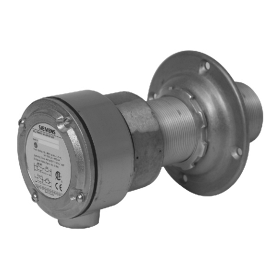
Milltronics Millpulse 600 Milltronics Millpulse 600 is a heavy-duty 2-wire motion sensor that provides a solid state switch output to a PLC . It is used primarily for monitoring the speed of rotating, reciprocating, or conveying equipment. Milltronics Millpulse 600 has a circuit card and magnet assembly potted in the probe body and comes complete with mounting flange and locknut. -
Page 7: Specifications
• red LED for switch status Construction • probe body: aluminum • process mounting: 2” NPSL • connection box: aluminum 3/4” NPT conduit entrance 4 screw terminals for maximum 12 AWG wire size • gasketing: neoprene 7ML19985DG02 Milltronics MillPulse 600 – INSTRUCTION MANUAL Page 3... - Page 8 • The use of approved watertight conduit hubs/glands is required for Type 4/NEMA 4, Type 4X/NEMA 4X, Type 6/NEMA 6, IP67 (outdoor applications). Weight • 2 kg (4.4 lbs.) Approvals • CE, CSA (C/US) • EMC performance available upon request Page 4 Milltronics MillPulse 600 – INSTRUCTION MANUAL 7ML19985DG02...
-
Page 9: Installation
It is advisable to keep the Milltronics Millpulse 600 away from high voltage or current runs, contactors and SCR drives. WARNING: Do not connect Milltronics Millpulse 600 directly to supply. -
Page 10: Interconnection
• A circuit breaker or switch in the building installation, marked as the disconnect switch, shall be in close proximity to the equipment and within easy reach of the operator. WARNING: All field wiring must have insulation suitable for at least 135 V. Page 6 Milltronics MillPulse 600 – INSTRUCTION MANUAL 7ML19985DG02... -
Page 11: Loading
Loading 7ML19985DG02 Milltronics MillPulse 600 – INSTRUCTION MANUAL Page 7... -
Page 12: Operation
Operation Milltronics Millpulse 600 works on the principle of Faraday’s Laws of Electromagnetic Induction. When a ferromagnetic object (target) enters the probe’s permanent magnetic field, it distorts the flux causing it to cut the coil windings, thereby generating a voltage. -
Page 13: Dimensions
6 mm (0.25”) dia. hole for 1/4-20 bolt or drill for 1/4-20 bolt on 114 and tap on 114 mm mm (4.5”) BCD, 4 places (4.5”) BCD, 4 places Note: Install safety shields where required. 7ML19985DG02 Milltronics MillPulse 600 – INSTRUCTION MANUAL Page 9... -
Page 14: Application
75 mm (3”) apart negligible side travel non-ferrous buckets with ferrous bolts or buckets greater than 75 mm (3”) apart Milltronics Millpulse 600 side Milltronics Millpulse 600 front or back mounting mounting Shafts key or keyway Milltronics Millpulse shaft Milltronics... -
Page 15: Belt Conveyors
The dimensions shown for the plate, window, and bracket are the minimum recommended. Use series 300 stainless steel, brass, or aluminum. Milltronics Millpulse 600 must not touch the plate if temperatures are in excess of 60 °C (140 °F). -
Page 16: Cleaning And Maintenance
Cleaning and Maintenance Millpulse 600 can be cleaned by wiping the enclosure exterior with a damp cloth. No other maintenance is required for this device. Page 12 Milltronics MillPulse 600 – INSTRUCTION MANUAL 7ML19985DG02... - Page 17 Notes...
- Page 18 Notes...
- Page 20 Siemens Milltronics Process Instruments Inc. Siemens Milltronics Process Instruments Inc. 2006 1954 Technology Drive, P .O. Box 4225 Subject to change without prior notice Peterborough, ON, Canada K9J 7B1 *7ml19985DG02* Rev. 2.0 Tel: (705) 745-2431 Fax: (705) 741-0466 Email: techpubs.smpi@siemens.com...
Need help?
Do you have a question about the Milltronics Millpulse 600 and is the answer not in the manual?
Questions and answers