Table of Contents
Advertisement
Quick Links
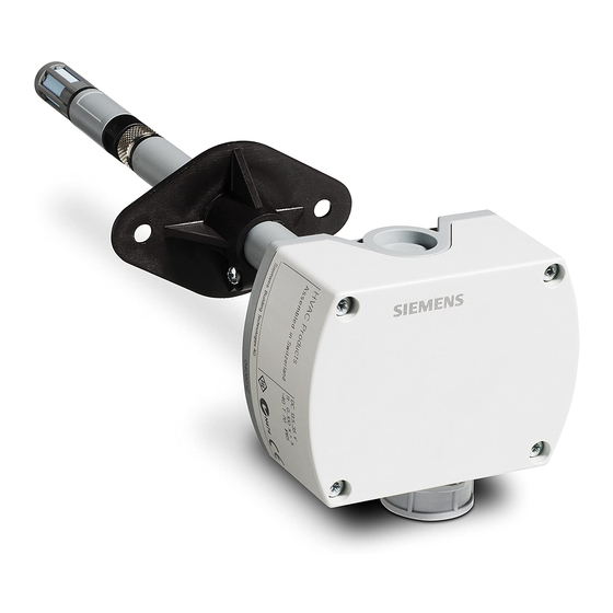
Q-Series Relative Humidity (RH) and
Relative Humidity & Temperature (RH/T) Duct Sensors
Product Description
Relative Humidity (RH) and Relative Humidity &
Temperature (RH/T) duct sensors monitor the
relative humidity or the relative humidity and
temperature in a duct, depending on the model.
Sensors are directly wired to the controller via
twisted pair and/or three conductor cables
(18 to 22 AWG). The number and type of cables
required depends on the model selected. All field
wiring is terminated in a terminal block on the sensor
body.
Product Numbers
Table 1. Relative Humidity Only.
Product
Humidity
Number
Signal
QFM2100
0 to 10 Vdc
QFM3100
QFM2101
4 to 20 mA
QFM3101
QFM4101
Table 2. Relative Humidity and Temperature.
Product
Temperature
Number
Signal
QFM2160
0 to 10 Vdc
QFM3160
QFM4160
QFM2171
QFM3171
4 to 20 mA
QFM4171
QFM2110
Pt 1KΩ
QFM2120
Ni 1KΩ
QFM2140
T1 PTC
QFM3110
Pt 1KΩ
Applies to humidity only
♦
NOTE:
Sensor tips on QFM31... and QFM41...
models are field replaceable.
Item Number 129-413, Rev. 011
♦
Accuracy
±5%
±2%
±5%
±2%
±2% Certified
Humidity
♦
Accuracy
Signal
±5%
0 to 10 Vdc
±2%
±2% Cert.
±5%
4 to 20 mA
±2%
±2% Cert.
±5%
0 to 10 Vdc
±2%
Installation Instructions
Additional Reference Documents
Product Number
QFM21...
QFM3160
QFM4160
Required Tools
•
Phillips screwdrivers, #1 and #2
•
Wire cutters/strippers
•
Medium flat-blade screwdriver
•
Tape measure
•
Medium-duty electric drill
•
Marker or pencil
•
No. 26 (0.147-inch) drill bit
•
Small level
•
7/8-inch drill bit or hole saw
•
Two No. 8 × 1-inch sheet metal screws
Expected Installation Time
One hour
Prerequisites
•
Ensure that the appropriate field wiring is
installed.
Appropriate wiring is one or more twisted
pairs, or three conductor cables (plenum or
non-plenum as required), within the
maximum wiring run length for the individual
equipment controller. The maximum
recommended length is 750 feet (229 m).
•
Ensure that all wiring complies with National
Electric Code (NEC) and local regulations.
Mounting Information
Locate the sensor:
•
In the center of a duct.
•
Away from fans, corners, heating and cooling
coils, and so on.
•
Where it receives adequate airflow for proper
operation.
Document No. 129-413
October 13, 2004
Technical Instructions
155-748
155-749
155-750
Page 1 of 3
Advertisement
Table of Contents

Related Manuals for Siemens QFM2100


Summary of Contents for Siemens QFM2100
-
Page 1: Installation Instructions
Product Humidity ♦ • 7/8-inch drill bit or hole saw Accuracy Number Signal • Two No. 8 × 1-inch sheet metal screws QFM2100 ±5% 0 to 10 Vdc QFM3100 ±2% Expected Installation Time QFM2101 ±5% 4 to 20 mA QFM3101 ±2%... - Page 2 Document No. 129-413 Installation Instructions October 13, 2004 • Direct installation: Instructions a. Remove the sensor cover. 1. Drill a 7/8-inch diameter hole into the duct at the b. Use the base as a template, and drill four desired location of the sensor. holes with a No.
-
Page 3: Wiring Diagrams
Information in this publication is based on current specifications. The company reserves the right to make changes in specifications and models as design improvements are introduced. Other product or company names mentioned herein may be the trademarks of their respective owners. © 2004 Siemens Building Technologies, Inc. Siemens Building Technologies, Inc.
Need help?
Do you have a question about the QFM2100 and is the answer not in the manual?
Questions and answers