
Related Manuals for Siemens BS-240


Summary of Contents for Siemens BS-240
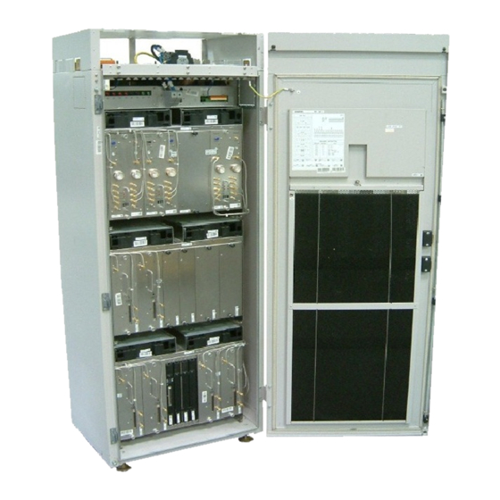
- Page 1 Information Base Station System Technical Description (TED:BSS) BS-240/241 A30808-X3247-L14-2-7618...
- Page 2 All designations used in this document can be trademarks, the use of which by third parties for their own purposes could violate the rights of their owners. Copyright (C) Siemens AG 2003. Issued by the Information and Communication Mobile Group Hofmannstraße 51...
- Page 3 Information Technical Description (TED:BSS) Base Station System BS-240/241 Reason for Update Summary: Second Edition for Release BR7.0 Details: Chapter/Section Reason for Update New Release BR7.0 Revised Chapter Issue History Issue Date of issue Reason for Update Number 07/2003 First Edition for new Release BR7.0 12/2003 Second Edition for Release BR7.0...
- Page 4 Technical Description (TED:BSS) Information BS-240/241 Base Station System A30808-X3247-L14-2-7618...
-
Page 5: Table Of Contents
Information Technical Description (TED:BSS) Base Station System BS-240/241 This document consists of a total of 70 pages. All pages are issue 2. Contents Introduction ..........9 Main Features . - Page 6 Technical Description (TED:BSS) Information BS-240/241 Base Station System 4.3.1 Functionality ..........63 FCC Issues (for US Market only) .
- Page 7 Fig. 2.2 Functional Blocks of the BS-240/241......15 Fig. 2.3 Redundant COREs and their Interfaces .
- Page 8 Technical Description (TED:BSS) Information BS-240/241 Base Station System Tables Tab. 1.1 Technical Data ..........12 Tab.
-
Page 9: Introduction
High receiver sensitivity is also guaranted. The modular architecture and the flexible internal structure, enables the BS-240/241 to provide new GSM features such as EDGE; this platform ensures that network evolution is as smooth as possible. -
Page 10: Main Features
Backup Batteries and Link Equipment. A Service Rack/Shelter can be equipped with AC/DC Converters. Easy Rack/Shelter Extension is possible with one or two Extension Racks/Shelters. The BS-240/241 can be configured for the systems GSM 850, GSM 900, GSM 1800 and GSM 1900 with the following configurations: –... - Page 11 SW Support of Core Redundancy – SW Support of BCCH Redundancy – AC/DC n+1 redundancy. (n+1) AC/DC Converters work in load sharing, but n AC/DC are able to supply the whole BS-240/241 including Service Racks/Shelters Abis interface: – Enhanced Full-Rate TCH –...
-
Page 12: Technical Data
Technical Description (TED:BSS) Information BS-240/241 Base Station System Technical Data The BS-240/241 family with 24 transceivers can be supplied in the following versions: – A BS-240 for indoor installation. – A BS-241 for outdoor installation (also equipped with: integrated power supply, battery, microwave equipment, integrated link equipment, heat exchanger and cross connector). -
Page 13: Frequency Bands
Information Technical Description (TED:BSS) Base Station System BS-240/241 Characteristics BS-240 (indoor) BS-241 (outdoor) -5 °C to +55 °C -45 °C to +50 °C Temperature range (˚C) +23 °F to +131 °F -49 °F to +122 °F Tab. 1.1 Technical Data... -
Page 14: Hardware Architecture
Base Station System 2 Hardware Architecture The BS-240/241 is designed to achieve commonality of boards to serve both GSM 850, GSM 900 with its different deviates (GSM 1800, GSM 1900) and standards selected for mobile communication systems. Moreover, the architecture of BS-240/241 provides maximum flexibility to develop large and small BTSs which have similar costs per TRX. -
Page 15: Fig. 2.2 Functional Blocks Of The Bs-240/241
Cascading DIAMCO RXDIV Service Rack LE 0 LE 1 AC/DC AC/DC ACTC ACTP DCB- DCB- CTRL CTRL CAN BUS BATTERY BATTERY not present in case of BTSE with reduced number of fan Fig. 2.2 Functional Blocks of the BS-240/241 A30808-X3247-L14-2-7618... - Page 16 The core boards provide functions common to all carriers within the BS-240/241 (e.g., clock generation, O&M processing,...) as well as LAPD processing for the different carriers.
-
Page 17: Board Redundancy
AC/DC Up to 6 AC/DC converters can be equipped in the service1 Rack which provide N+1 redundancy. AC/DC converters work in load sharing, but n AC/DC are able to supply the whole BS-240/241. 2.1.2 Core The Core can consist of up to 2 (without redundancy) or up to 4 (with redundancy) boards, which have a common backplane. -
Page 18: Power Amplifier Output Level (Typical Values)
Technical Description (TED:BSS) Information BS-240/241 Base Station System switch over, the SELICs on the active CORE are disabled by the switch logic and the SELICs on the passive one are enabled. The SELICs on the CORE have to know whether they are on the active or on the passive CORE. For this reason the SELICs need a active/passive pin, which is served by the redundancy switch logic. -
Page 19: Rack Configuration
Watt (GMSK) / 32 Watt (8PSK). The mentioned data are guaranteed from Module Factory Test only. Rack Configuration The BS-240/241 family, with 8 transceivers per Rack, which is expandable up to 24 transceivers in 3 Racks and can be supplied in two versions: –... -
Page 20: Fig. 2.4 Bs-240 Base Rack And 2 Extension Racks
FAN 3 FAN 2 FAN 3 FAN 4 * FAN 5* FAN 4* FAN 5* FAN 4* FAN 5* * not present in case of BTSE with reduced number of fans Fig. 2.4 BS-240 Base Rack and 2 Extension Racks A30808-X3247-L14-2-7618... -
Page 21: Fig. 2.5 Bs-241 Base Rack And 2 Extension Racks
Information Technical Description (TED:BSS) Base Station System BS-240/241 SIEMENS BS-241 SIEMENS BS-241 SIEMENS BS-241 DC-PANEL DC-PANEL DC-PANEL ACT-C ACT-C ACT-C FAN 0 FAN 1 FAN 1 FAN 0 FAN 1 FAN 0 FAN 2 FAN 3 FAN 2 FAN 3... -
Page 22: Fig. 2.6 Possible Configuration Of Service1 Rack And Service2 Rack
Technical Description (TED:BSS) Information BS-240/241 Base Station System SIEMENS SIEMENS DC-PANEL DC-PANEL ACT-C ACT-C FAN 0 FAN 1 FAN 0 FAN 1 LE 0 LE 1 LE 2 LE 3 LE 4 AC + DC Distribution LE 5 FAN 2... -
Page 23: Fig. 2.7 Bs-240/241 Fully Equipped With 24 Carriers
Base Rack Extension Rack Extension Rack Fig. 2.7 BS-240/241 fully Equipped with 24 Carriers For the BS-241 outdoor cabinet only one type of the Shelter exists to be used for all outdoor Base Shelter, Extension Shelters, Service1 and Service2 Shelters. A30808-X3247-L14-2-7618... -
Page 24: Description Of Modules
Technical Description (TED:BSS) Information BS-240/241 Base Station System 3 Description of Modules Name Freq. Remarks Var. Core modules: Up to 8 PCM lines with COBA and COSA COBA Core basis equipped (COBA and COSA can be COSA Core satellite equipped only in the Base Rack/Shelter). -
Page 25: Core (Coba And Cosa)
Information Technical Description (TED:BSS) Base Station System BS-240/241 Name Freq. Remarks Var. Cover Parts: Cover Parts have to be the air flow inside the Frame or Shelter is CP:ACOM inserted if the respective not affected CP:CU active module is not... -
Page 26: Fig. 3.1 Backplane Slot Configuration Of Core
Technical Description (TED:BSS) Information BS-240/241 Base Station System Base Rack Extension Racks OVPT CABLES Backplane Plugs COBA Abis COSA COBA red. COSA red 6 Abis 2 Abis 6 Abis 2 Abis other SELIC SELIC SELIC SELIC interfaces Fig. 3.1 Backplane Slot Configuration of Core For a configuration with less or equal 2 PCM30/24-interfaces and no Extension Rack one COBA-board is required. -
Page 27: Core Basis (Coba2P8)
Information Technical Description (TED:BSS) Base Station System BS-240/241 HW inside the Rack is disturbed (no loss of data on other boards) or a board is destroyed. A COBA-board can only be pulled out, if before the COSA-board is pulled out After plug-in of a Core-board, this board is in the reset-state and all bus-drivers of external busses are in tristate. -
Page 28: Fig. 3.3 Structure Of Aclk Function
Technical Description (TED:BSS) Information BS-240/241 Base Station System reference clock to redundant ACLK reference reference clock input clock phase/ divider OCVCXO master clock frequency master 32, 768 MHz detector clock tracking divider oscillator processor BCC interface controlled master sync input... -
Page 29: Core Satellite (Cosa6P16)
Information Technical Description (TED:BSS) Base Station System BS-240/241 possible. The communication path from the LMT to the BCC is not affected, i.e., a SW-download via the LMT is possible. 3.1.2 Core Satellite (COSA6P16) The COSA6P16 board (COSA6P16) has the following characteristic: –... -
Page 30: Carrier Unit (Cu)
Technical Description (TED:BSS) Information BS-240/241 Base Station System The COSA6P16 is switched with relays to the PCM-lines. In case of failures, the PCM-port 1(3)(5) and 2(4)(6) can be connected with each other via appropriate relays. There is a power-on device on the COSA6P16, which generates a reset at power-on (board-reset). -
Page 31: Fig. 3.6 Patrx Block Diagram
Information Technical Description (TED:BSS) Base Station System BS-240/241 RXFEM to SIPRO for Rx input downconversion (diversity) to baseband RXFED RXLO LCLK from SIPRO TXLO RF Control from SIPRO Tx output MODUP PWSTG GMSK modulated signal from SIPRO TXBB PWRDET from SIPRO Fig. -
Page 32: Edge Carrier Unit
Technical Description (TED:BSS) Information BS-240/241 Base Station System frames and sent to TRAU. Signalling data (e.g., FACCH) are processed by layer 3 of BTS software – receives the TRAU frames or signalling data. The TRAU frames are unformatted and sent to the coder. After encoding, data are ciphered. Now, baseband hopping takes place. -
Page 33: Gmsk/8Psk Linear Modulation
The mechanical design of ECU is identical to that of CU versions. ECU and CU modules may be installed in any kind of mixed configurations concerning BS-240/241 hardware (Base/Extension Racks). Further, any cell/sector configuration with a mixture of EDGE CU and “normal CUs” can be implemented. -
Page 34: Fig. 3.8 Epatrx And Esipro Function Block Diagram
Technical Description (TED:BSS) Information BS-240/241 Base Station System Fig. 3.8 EPATRX and ESIPRO Function Block Diagram EDGE Power Amplifier and Tranceiver Unit ( EPATRX) EPATRX provides the main analog functions of the CU. In uplink direction, two (diver- sity) preamplified and filtered RF signals are received from the antenna combining equipment. - Page 35 Information Technical Description (TED:BSS) Base Station System BS-240/241 ECU is supported by the module LTL, which provides an RF loop between downlink and uplink path. Signal Processing Unit (ESIPRO) The ESIPRO-Board of the BTSPLUS is a part of the EDGE Carrier Unit. It contains the following functions of the EDGE Carrier Unit: –...
-
Page 36: Fig. 3.9 Data Flow In Esipro
Technical Description (TED:BSS) Information BS-240/241 Base Station System Fig. 3.9 Data Flow in ESIPRO EPSU (Power Supply Unit) The EPSU is the DC/DC converter for the ECU for all applications. The EPSU generates the voltages +26V/+28V, +12V, +5,3V and -5,3V for the analog circuitry and +3.3V for the digital circuitry from a -48V primary input voltage. -
Page 37: Gmsk Carrier Units (Gcu)
Information Technical Description (TED:BSS) Base Station System BS-240/241 GMSK Carrier Units (GCU) The GCU is a resembled ECU (the main sub-units are similar) which supports GMSK modulation only, like the CU. GCUs and CUs differ in the RF output power value for the GSM 1800 frequency band: GCU: 53,7 W;... -
Page 38: Di(=2) Amplifier Multi Coupler (Diamco)
Technical Description (TED:BSS) Information BS-240/241 Base Station System DI(=2) Amplifier Multi Coupler (DIAMCO) For the uplink direction, the DIAMCO is used to filter and distribute the received signals to the Carrier Units in one Rack. The DIAMCO consists of two branches constituted by: –... -
Page 39: High Power Duplexer Unit (Hpdu)
Information Technical Description (TED:BSS) Base Station System BS-240/241 – the TX parts of the duplex filter The DC power for the TMA is feed into the triplexer by the PDU (Power Distribution Unit) functionality of the DUAMCO/DIAMCO. The Encoder/Decoder units of the TMA signalling interface generate an alarm for each TMA separately by supervising the DC current consumption of each unit. -
Page 40: Ac/Dc Converter (Ac/Dc)
Technical Description (TED:BSS) Information BS-240/241 Base Station System 8 bit µC (80C505C) for initialization, supervision and controlling the functions of the – ACT. – PID-EEPROM to store board data. The physical function of the ACT is to interface the alarm and command signals between the CAN-BUS and the alarm and command connectors. -
Page 41: Dc And Battery Controller (Dcbctrl)
Overvoltage Protection and Tracer (OVPT) The OVPT is responsible for lightning protection of the PCM24/PCM30 ports of the Abis interface and the external synchronization clock input of the BS-240/241 against over voltage. Additionally, the OVPT provides interfaces to connect PCM tracers without interruption for monitoring the Abis lines. -
Page 42: Abis Link Equipment (Le)
If a link equipment is available at the telecommunication site, possibly no link equipment is necessary. If BS-240/241 is installed away from a telecommunication site the link equip- ment must be installed inside the Service Rack/Shelter. If radio transmission is required, microwave equipment must be used. -
Page 43: Fan
Information Technical Description (TED:BSS) Base Station System BS-240/241 Battery System 0 Battery 0 Battery 1 Battery 2 Base Frame for AC/DC Converter Battery System 1 Battery 0 Battery 1 Battery 2 Battery System 2 Battery 0 Battery 1 Battery 2... -
Page 44: Heat Exchanger (Hex)
Technical Description (TED:BSS) Information BS-240/241 Base Station System In order to keep both the acoustic noise and the power consumption of all fans at the lowest level possible, the fan speeds are (independently of each other) temperature controlled via integrated sensors (NTC) that monitor the critical hotspots in order to keep them in an acceptable range. -
Page 45: Antenna Combiners And Receiving Paths
Information Technical Description (TED:BSS) Base Station System BS-240/241 4 Antenna Combiners and Receiving Paths Methods of Combining In order to serve cells with different carrier numbers, certain combinations of combining modules are required. These configurations provide the necessary performance in a cost effective way. - Page 46 Technical Description (TED:BSS) Information BS-240/241 Base Station System The receive path consists of a LNA (Low Noise Amplifier) and a power splitter. The LNA takes care of a low system noise figure and consists of two branches. In case of malfunction of one amplifier, the RX gain of the DUAMCO decreases by about 6 dB.
- Page 47 Information Technical Description (TED:BSS) Base Station System BS-240/241 Antenna 1 Antenna 0 Module 0 Module 1 Bias Bias MUCO MUCO Signall. AMCO AMCO DC/DC Control DC interf. RXCA from RXCA from to Rx to Rx Fig. 4.2 DUAMCO 2:2 Antenna 0...
- Page 48 Technical Description (TED:BSS) Information BS-240/241 Base Station System Antenna 0 Antenna 1 Module 0 Module 1 BIAS BIAS MUCO MUCO Signall. AMCO AMCO Coupler Coupler DC/DC Control CAN bus DC interf. RXCA RXCA from from to Rx to Rx to/from core Fig.
- Page 49 Information Technical Description (TED:BSS) Base Station System BS-240/241 Therefore, the number of base modules is equal to the number of cells the FICOM has to support. The number of expansion modules per cell depends on the total number of carriers per cell (2,4,6 or 8).
- Page 50 Technical Description (TED:BSS) Information BS-240/241 Base Station System modulated onto a IF carrier at 7.86 MHz: This interface is identical to the interface between DUAMCO and TMA. The DIAMCO RX amplifier has two different operation modes, depending on the exist- ence of TMAs.
- Page 51 Information Technical Description (TED:BSS) Base Station System BS-240/241 High Power Duplexer (HPDU2) The High Power Duplexer has the task of combining the TX and the RX paths into one antenna, in order to minimize the number of antennas when FICOM is used. The HPDU contains a duplex filter for the transmit frequency band and for the receive frequency band, but no Low Noise Amplifier in the RX path.
-
Page 52: Typical Combiner Losses (Tx Path) And Output Power Level
Technical Description (TED:BSS) Information BS-240/241 Base Station System TX/RX Antenna Antenna DUBIAS HPDU FICOM DIAMCO CU0 CU1 RX0 RX1 Fig. 4.8 Configuration with HPDU, DUBIAS and TMA Diplexer The Diplexer gives the possibility to use one Antenna Feeder Cable for both GSM 850, GSM 900 and GSM 1800, GSM 1900 frequencies. - Page 53 Information Technical Description (TED:BSS) Base Station System BS-240/241 DUAMCOs operating with the minimum guaranteed input power from CU: GSM 850, GSM 900: n x 50 W; GSM 1800, GSM 1900: n x 35 W The typical value for the insertion loss of FICOMs is better than 3 dB with an uncritical carrier configuration (carrier spacing >...
-
Page 54: Duamco - Diamco Gain (Rx Path)
Technical Description (TED:BSS) Information BS-240/241 Base Station System 4.1.2DUAMCO - DIAMCO GAIN (RX Path) DUAMCO - DIAMCO gain DUAMCO gain GSM 850, GSM, GSM 1800, GSM P-GSM,GSM-RE, GSM-PS 1900 AMCO characteristics Gain (ANT-RX) 20 dB +/-1.5 dB 22 dB +/-1.5 dB Gain (ANT-RXCA) 18.5 dB +/-1.5 dB... -
Page 55: Parameters Of Tower Mounted Amplifier (Tma)
Information Technical Description (TED:BSS) Base Station System BS-240/241 4.1.3 Parameters of Tower Mounted Amplifier (TMA) 900 MHz Tower Mounted Amplifier Electrical System Specified Typical Uplink RF-band 890- 915 MHz Return Loss (ANT / BTS port) > 14 dB > 15 dB Return Loss by- pass mode >... - Page 56 Technical Description (TED:BSS) Information BS-240/241 Base Station System 1800 MHz Tower Mounted Amplifier Electrical System Specified Typical Uplink RF-band 1710 - 1785 MHz Return Loss (ANT / BTS port) > 14 dB > 16 dB Return Loss by- pass mode >...
-
Page 57: Examples Of Possible Btse Configurations
Information Technical Description (TED:BSS) Base Station System BS-240/241 Mechanical Size, W x H x D 172x280x191 mm (8"x11"x7.5") Weight 4.25 kg (9 Lbs) Antenna connector 7/ 16 BTS connector 7/ 16 General Supply Voltage Range +12V +/- 8% Alarm functions alarming via sub-carrier to DUAMCO or DIAMCO CIN is part of the combining units DUAMCO or DIAMCO and values are incorporated in the units specs. -
Page 58: Fig. 4.10 Multi-Cell (3,3,2): With 2 Duamco 4:2 And 1 Duamco 2:2
Technical Description (TED:BSS) Information BS-240/241 Base Station System CELL 0 CELL 1 CELL 2 DUAMCO 4:2 DUAMCO 4:2 DUAMCO 2:2 RX TX RX TX RX TX CU0 CU1 CU3 CU4 CU6 CU7 Fig. 4.10 Multi-cell (3,3,2): with 2 DUAMCO 4:2 and 1 DUAMCO 2:2... -
Page 59: Fig. 4.12 Single-Cell (8,0,0): With 2 Duamco 4:2
Information Technical Description (TED:BSS) Base Station System BS-240/241 CELL 0 DUAMCO 4:2 DUAMCO 4:2 RX TX RX TX CU0 CU1 CU2 CU3 CU4 CU5 CU6 CU7 Fig. 4.12 Single-cell (8,0,0): with 2 DUAMCO 4:2 CELL 0 CELL 1 CELL 2... -
Page 60: Fig. 4.14 Single-Cell (11
Technical Description (TED:BSS) Information BS-240/241 Base Station System HPDU RX - Filter TX - Filter FICOM FICOM FICOM FICOM Base Expansion Expansion Expansion DIAMCO DIAMCO Module Module Module Module CU0 CU1 CU2 CU3 CU4 CU5 CU6 CU7 RACK 0 HPDU... -
Page 61: Receiving Paths
DIAMCO use a Low Noise Amplifier (LNA) in the RX path, which can be set to different gain to establish the various configurations of the BS-240/241. Additionally, the DUAMCO and DIAMCO have power supply and supervision functionality for a Tower Mounted Amplifier. -
Page 62: Receiver Sensitivity
Technical Description (TED:BSS) Information BS-240/241 Base Station System The principle of On Air Combining will also be used, if TX combining beyond the Rack borders is required. For e.g. to combine 24 carriers, belonging to the same cell, 3 FICOMs will be used, each combines 8 carriers to one antenna. Combining of the signals from the 3 antennas takes place 'On Air'. -
Page 63: Fig. 4.15 Capacity Downlink Improvements For Tx Diversity
Information Technical Description (TED:BSS) Base Station System BS-240/241 Fig. 4.15 Capacity Downlink Improvements for TX Diversity 4.3.1Functionality The fully equipped BTS site with combined CU pairs to apply transmission diversity keeps up with later capacity requirements and helps operate the BTS sites in temporarily adjustable modes of operation. -
Page 64: Fig. 4.16 Bts Rack Cabling For Transmitter Diversity Operation
Technical Description (TED:BSS) Information BS-240/241 Base Station System CUs use separate antennas. A distance preferably higher than ten lambdas separates the antennas when combining on-air transmissions. The following example illustrates CU co-location in an extended circular cell that provides an increased cell capacity by using several different carrier frequency bands (e.g. -
Page 65: Fcc Issues (For Us Market Only)
Information Technical Description (TED:BSS) Base Station System BS-240/241 exclude time slots or logical channels from applying the transmission diversity time delay. FCC Issues (for US Market only) In this chapter you find the maximum output power at the antenna connector of the BTS.These values are only relevant for the US market. -
Page 66: Maximum Rf Power Output Values
Technical Description (TED:BSS) Information BS-240/241 Base Station System CU Type Carrier Channel Maximum RF Maximum RF Frequency Power Output Power Output [MHz] GMSK 8PSK ECUPHPV3 1930.2 39.6 dBm = 9.1 W 42.7 dBm = 18.6 W ECUPHPV3 1989.8 41.8 dBm = 15.1 W 44.9 dBm = 30.9 W ECUPHPV2 1930.2... -
Page 67: Power Supply And Battery Backup
Support of Emergency Operation for 3rd Party BBU System In the BS-240/241 implementation the switch into emergency configuration (due to a battery discharge alarm) is triggered by an "ALARM STATUS" CAN bus message that has been received from the CAN node of the AC/DC controller. - Page 68 Technical Description (TED:BSS) Information BS-240/241 Base Station System A special setting of the attribute "associatedString" in the command "CREATE ENVABTSE" for the corresponding site input allows the operator to indicate that the support of emergency configuration is required for the 3rd party battery backup unit system.
- Page 69 Information Technical Description (TED:BSS) Base Station System BS-240/241 Abbreviations Alternate Current Authentication Centre ACLK Advanced Clock ACOM Antenna Combiner AC Panel ACTC Alarm Collection Terminal Connection module ACTM Alarm Collection Terminal for Master Rack ACTP Alarm Collection Terminal for Slave Rack...
- Page 70 Technical Description (TED:BSS) Information BS-240/241 Base Station System Low Noise Amplifier Loadable Timing Generation Local Test Loop Low Voltage Detect MODUP Modulator and Upconverter MUCO Multi Coupler Negative Thermal Coefficient O&M Operation and Maintenance OCVCXO Oven Controlled VCXO Operation and Maintenance Terminal...
Need help?
Do you have a question about the BS-240 and is the answer not in the manual?
Questions and answers