Peak PCAN-PC/104-Plus User Manual
Can interface for pc/104-plus
Hide thumbs
Also See for PCAN-PC/104-Plus:
- User manual (35 pages) ,
- User manual (34 pages) ,
- User manual (22 pages)

Related Manuals for Peak PCAN-PC/104-Plus


Summary of Contents for Peak PCAN-PC/104-Plus
- Page 1 PCAN-PC/104-Plus CAN Interface for PC/104-Plus User Manual Document version 2.5.0 (2019-03-06)
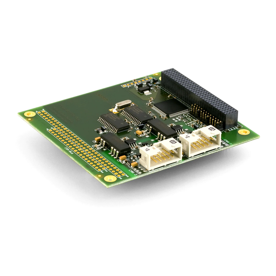
- Page 2 IPEH-002097 Channel opto-decoupled isolation for CAN connections The cover picture shows the product PCAN-PC/104-Plus Dual Channel opto- decoupled. Other product versions have an identical form factor but vary in equipment. On request you can get the product versions with stack-through connectors for the ISA bus.
-
Page 3: Table Of Contents
PCAN-PC/104-Plus – User Manual Contents Introduction Properties at a Glance System Requirements Scope of Supply Configuring and Installing the Card and the Software Configuring the Card 2.1.1 Setting the Position in the PC/104 Stack Installing the Software and the Card... - Page 4 PCAN-PC/104-Plus – User Manual Technical Specifications Appendix A CE Certificate Appendix B Dimension Drawing Appendix C Quick Reference...
-
Page 5: Introduction
PCAN-PC/104-Plus – User Manual Introduction The PCAN-PC/104-Plus card enables the connection of one or two CAN networks to a PC/104-Plus system. Up to four cards can be operated, with each piggy-backing off the next. The CAN bus is connected using a 9-pin D-Sub plug on the slot bracket supplied. -
Page 6: System Requirements
Extended operating temperature range from -40 to 85 °C (-40 to 185 °F) Optionally available: PCI/104-ISA stack-through connector Note: This manual describes the use of the PCAN-PC/104-Plus card with Windows. You can find device drivers for Linux and the corresponding application information on the provided DVD in the directory branch Develop and on our website under www.peak-system.com/linux. -
Page 7: Scope Of Supply
PCAN-PC/104-Plus – User Manual Scope of Supply PCAN-PC/104-Plus card Slot bracket with D-Sub connectors for the CAN bus Device drivers for Windows 10, 8.1, 7, and Linux (32/64-bit) Device driver for Windows CE 6.x (x86 and ARMv4 processor support) CAN monitor PCAN-View for Windows... -
Page 8: Configuring And Installing The Card And The Software
This chapter covers the configuration and the software setup for the PCAN-PC/104-Plus card under Windows and the installation of the card in the PC/104 stack. Note: Under Windows the PCAN-PC/104-Plus card is run as a PCI card. Configuring the Card Before installing the PCAN-PC/104-Plus card into a PC/104 stack, you may have to configure it using jumpers on the PCB. - Page 9 PCAN-PC/104-Plus – User Manual Figure 1: Position of the jumpers J7, J8, J9 on the PCAN-PC/104-Plus card Position in the PC/104 stack Jumper Signal ID Select Clock Select Interrupt Select...
-
Page 10: Installing The Software And The Card
PCAN-PC/104-Plus – User Manual Installing the Software and the Card This chapter covers the software setup for the PCAN-PC/104-Plus and the installation of the card in the PC/104 stack. Install the driver before you install the card. Do the following to install the driver: Start Intro.exe from the supplied DVD. - Page 11 PCAN-PC/104-Plus – User Manual Do the following to install card into the PC/104 stack: Attention! Electrostatic discharge (ESD) can damage or destroy components on the card. Take precautions to avoid ESD. Plug a cable from the slot bracket to a 10-pin socket for each CAN connection.
-
Page 12: Notes For The Isa Bus Stack-Through Connection
Do the following to check the operational readiness: Open the Windows Start menu. Type peakcpl and press Enter . The information window for PEAK hardware appears. The plug-in card must be displayed in the table on the CAN Hardware tab. Notes for the ISA Bus Stack-through... -
Page 13: Connecting The Can Bus
PCAN-PC/104-Plus – User Manual Connecting the CAN Bus Connection over D-Sub connector A High-speed CAN bus (ISO 11898-2) is connected to the 9-pin D-Sub connector. The pin assignment for CAN corresponds to the specification CiA® 303-1. Figure 3: Pin assignment High-speed CAN bus (view onto a D-Sub connector of the slot bracket) Low power devices (e.g. - Page 14 +5 V (optional) not connected not connected Tip: Connect a CAN bus with a different transmission standard via a bus converter. PEAK-System offers different bus converter modules (e.g. PCAN-TJA1054 for a Low-speed CAN bus according to ISO 11898-3).
-
Page 15: Slot Bracket With D-Sub Connectors
Figure 5: Single channel slot bracket Figure 6: Dual channel slot bracket To connect a CAN bus to the PCAN-PC/104-Plus card, use the supplied slot brackets. After you have connected the cables from the slot bracket with the 10-pin sockets, you can connect the CAN... -
Page 16: Voltage Supply Of External Devices
CAN connector (independently for each connector on the Dual Channel versions). With a solder bridge per CAN channel on the PCAN-PC/104-Plus board, a 5-Volt supply can optionally be routed to pin 1 and/or pin 9 of the D-Sub connector. - Page 17 PCAN-PC/104-Plus – User Manual Figure 7: Positions of the solder fields on the PCAN-PC/104-Plus card for a 5-Volt supply (JP1 upper position, JP2 lower position) 5-Volt supply D-Sub connector Solder field Without Pin 1 Pin 9 Pin 1 and (Standard)
-
Page 18: Cabling
The termination prevents interfering signal reflections and ensures the proper operation of the transceivers of the connected CAN nodes (CAN interfaces, control devices). The PCAN-PC/104-Plus card does not have an internal termination. Use the card on a terminated CAN bus. 3.3.2... -
Page 19: Maximum Bus Length
PCAN-PC/104-Plus – User Manual 3.3.3 Maximum Bus Length High-Speed-CAN networks may have bit rates of up to 1 Mbit/s. The maximum bus length depends primarily on the bit rate. The following table shows the maximum possible CAN bus length at different bit rates:... -
Page 20: Software And Api
PCAN-PC/104-Plus – User Manual Software and API This chapter covers the provided software PCAN-View and the programming interface PCAN-Basic. Monitor Software PCAN-View PCAN-View is simple Windows software for viewing, transmitting, and logging CAN and CAN FD messages. Note: This chapter describes the use of PCAN-View with a CAN adapter. - Page 21 PCAN-PC/104-Plus – User Manual Do the following to start and initialize PCAN-View: Open the Windows Start menu and select PCAN-View. The Connect dialog box appears. Figure 10: Selection of the hardware and parameters Select an interface from the list. From the drop-down list, select the Bit rate that is used by all nodes on the CAN bus.
-
Page 22: Receive/Transmit Tab
PCAN-PC/104-Plus – User Manual 4.1.1 Receive/Transmit Tab Figure 11: Receive/Transmit Tab The Receive/Transmit tab is the main element of PCAN-View. It contains two lists, one for received messages and one for the transmit messages. The CAN data format is hexadecimal by default. - Page 23 PCAN-PC/104-Plus – User Manual Enter the ID, the data Length, and the CAN message Data. Note: With the program version 4 of PCAN-View, the DLC field was renamed to Length. Latter reflects the actual data length. Enter a value into the Cycle Time field to choose manually or periodically message transmission.
-
Page 24: Trace Tab
PCAN-PC/104-Plus – User Manual 4.1.2 Trace Tab Figure 13: Trace Tab On the Trace tab, the data tracer (data logger) of PCAN-View is used for logging the communication on a CAN bus. During this process the messages are cached in the working memory of the PC. -
Page 25: Pcan-Pc/104-Plus Tab
PCAN-PC/104-Plus – User Manual 4.1.3 PCAN-PC/104-Plus Tab Figure 14: PCAN-PCI tab (example) The PCAN-PC/104-Plus tab contains some detailed information about the hardware and driver. 4.1.4 Status Bar Figure 15: Display of the Status Bar The status bar shows information about the current CAN connection, about error counters (Overruns, QXmtFull) and shows error messages. -
Page 26: Linking Own Programs With Pcan-Basic
On the provided DVD, you can find files of the PCAN-Basic programming interface in the directory branch Develop. This API provides basic functions for linking own programs to CAN and CAN FD interfaces by PEAK-System and can be used for the following operating systems: Windows 10, 8.1, 7 (32/64-bit) Windows CE 6.x (x86/ARMv4) -
Page 27: Features Of Pcan-Basic
Use of up to 16 channels for each hardware unit (depending on the PEAK CAN interface used) Simple switching between the channels of a PEAK CAN interface Driver-internal buffer for 32,768 messages per CAN channel Precision of time stamps on received messages up to 1 μs (depending on the PEAK CAN interface used) Supports PEAK-System‘s trace formats version 1.1 and 2.0 (for... -
Page 28: Principle Description Of The Api
PCAN-PC/104-Plus – User Manual Extended system for debugging operations Multilingual debugging output Output language depends on operating systems Debugging information can be defined individually Tip: An overview of the API functions is located in the header files. You can find detailed information about the PCAN-Basic API on the provided DVD in the text and help files (file name extensions .txt and .chm). -
Page 29: Notes About The License
Notes about the License Device drivers, the interface DLL, and further files needed for linking are property of the PEAK-System Technik GmbH and may be used only in connection with a hardware component purchased from PEAK-System or one of its partners. If a CAN hardware component... - Page 30 Controller NXP SJA1000 Transceiver NXP PCA82C251 Galvanic isolation PCAN-PC/104-Plus: none PCAN-PC/104-Plus opto: up to 500 V, separate for each CAN channel Supplying external PCAN-PC/104-Plus: D-Sub pin1 / 9; 5 V, max. 100mA devices PCAN-PC/104-Plus opto: D-Sub pin1 / 9; 5 V, max. 50mA...
- Page 31 PCAN-PC/104-Plus – User Manual Measures Dimension about 90 x 96 x 15 mm; (stacking height; component height max. 11 mm) See also dimension drawing in Appendix B on page 33 Weight PCAN-PC/104-Plus Single Channel: 46 g PCAN-PC/104-Plus Dual Channel: 50 g...
- Page 32 PCAN-PC/104-Plus – User Manual Appendix A CE Certificate...
- Page 33 PCAN-PC/104-Plus – User Manual Appendix B Dimension Drawing Figure 17: Dimension drawing PCAN-PC/104-Plus. The figure doesn't show the actual size of the product.
- Page 34 Check the operational readiness. Open the Windows Start menu. Type peakcpl and press Enter . An information window for PEAK Hardware opens. The plug-in card must be displayed in the table on the CAN Hardware tab. Getting started under Windows Run the CAN monitor PCAN-View from the Windows Start menu as a sample application for accessing the PCAN-PC/104-Plus card.
Need help?
Do you have a question about the PCAN-PC/104-Plus and is the answer not in the manual?
Questions and answers