
Related Manuals for Peak PCAN-USB FD


Summary of Contents for Peak PCAN-USB FD
- Page 1 PCAN-USB FD CAN FD Interface for High-Speed USB 2.0 User Manual Document version 1.3.2 (2018-02-22)
- Page 2 Part number PCAN-USB FD IPEH-004022 PCAN® is a registered trademark of PEAK-System Technik GmbH. CANopen® and CiA® are registered community trade marks of CAN in Automation e.V. All other product names mentioned in this document may be the trademarks or registered trademarks of their respective companies.
-
Page 3: Table Of Contents
PCAN-USB FD – User Manual Contents Introduction Properties at a Glance System Requirements Scope of Supply Installing the Software and the Adapter Connecting the CAN Bus Connection over D-Sub Connector Voltage Supply of External Devices Activating the Internal Termination Cabling 3.4.1... - Page 4 PCAN-USB FD – User Manual 5.2.2 Principle Description of the API 5.2.3 Notes about the License Technical Specifications Appendix A CE Certificate Appendix B Dimension Drawings Appendix C Quick Reference...
-
Page 5: Introduction
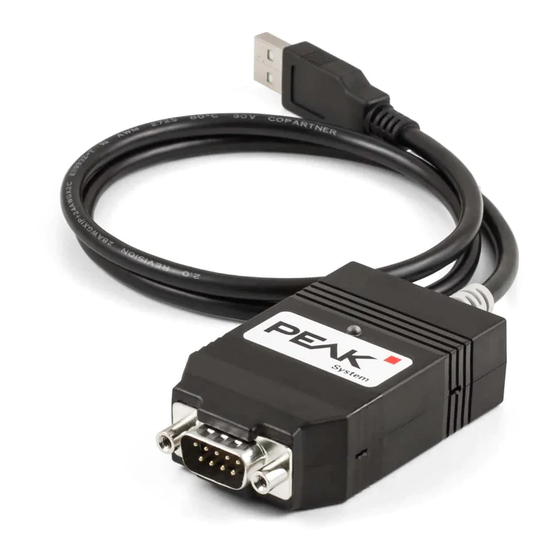
PCAN-USB FD – User Manual Introduction The CAN FD adapter PCAN-USB FD allows the connection of CAN FD and CAN networks to a computer via USB. A galvanic isolation of up to 500 Volts decouples the PC from the CAN bus. The simple handling and its compact plastic casing make the adapter suitable for mobile applications. - Page 6 Extended operating temperature range from -40 to 85 °C (-40 to 185 °F) Note: This manual describes the use of PCAN-USB FD adapter with Windows. You can find device drivers for Linux and the corresponding application information on the provided DVD in the directory branch Develop and on our website under www.peak-system.com/linux.
-
Page 7: System Requirements
PCAN-USB FD – User Manual System Requirements A vacant USB port (USB 1.1, USB 2.0 or USB 3.0) at the compu- ter or at a self-powered USB hub connected to the computer Operating system Windows 10, 8.1, 7 (32/64-bit) or Linux (32/64-bit) Note: Do not use a USB extension cable to connect the PCAN- USB FD adapter to the computer. -
Page 8: Installing The Software And The Adapter
PCAN-USB FD – User Manual Installing the Software and the Adapter This chapter covers the software setup for the PCAN-USB FD adapter under Windows and the connection of the adapter to the computer. Install the driver before you connect the adapter to the computer. -
Page 9: Connecting The Can Bus
CiA® 303-1. Figure 1: Pin assignment High-speed CAN (view onto connector of the PCAN-USB FD adapter) Low power devices (e.g. bus converters) can be supplied directly with 5 volts over pin 1 of the CAN connector. Pin 1 is not in use at the delivery state. -
Page 10: Voltage Supply Of External Devices
External devices with low power consumption (e.g. bus converters) can be directly supplied via the CAN connector. With a solder bridge for the one CAN channel on the PCAN-USB FD board (casing opened), a 5-Volt supply can optionally be routed to pin 1 of the D- Sub connector. - Page 11 PCAN-USB FD – User Manual Figure 2: Top view PCAN-USB FD board, solder field JP4 Risk of short circuit! The 5-Volt supply is not protected separately. Therefore, turn off the computer before you connect and disconnect CAN cables or peripheral systems.
-
Page 12: Activating The Internal Termination
PCAN-USB FD – User Manual Activating the Internal Termination The internal termination can be activated by solder jumpers on the board to terminate one end of the CAN bus with 120 Ohms. At delivery the termination is not activated. A High-speed CAN bus (ISO 11898-2) must be terminated on both ends with 120 Ohms. - Page 13 PCAN-USB FD – User Manual Figure 3: Top view PCAN-USB FD board, solder fields JP1 and JP2...
-
Page 14: Cabling
120 ohms on both ends. The termination prevents interfering signal reflections and ensures the proper operation of the transceivers of the connected CAN nodes (CAN interfaces, control devices). The PCAN-USB FD adapter has an optional internal termination with 120 ohms. For more information, see chapter 3.3. 3.4.2... -
Page 15: Maximum Bus Length
PCAN-USB FD – User Manual 3.4.3 Maximum Bus Length High-Speed CAN networks may have bit rates of up to 1 Mbit/s. The maximum bus length depends primarily on the bit rate. The following table shows the maximum possible CAN bus length... -
Page 16: Operation
PCAN-USB FD – User Manual Operation Status LED The PCAN-USB FD adapter has a status LED which can be in one of the following conditions: Status Meaning Green There's a connection to a driver of the operating system. Green slow blinking A software application is connected to the adapter. -
Page 17: Software And Api
PCAN-USB FD – User Manual Software and API This chapter covers the provided software PCAN-View and the programming interface PCAN-Basic. Monitor Software PCAN-View PCAN-View is simple Windows software for viewing, transmitting, and logging CAN- and CAN FD messages. Note: This chapter describes the use of PCAN-View with a CAN- FD adapter. - Page 18 PCAN-USB FD – User Manual Do the following to start and initialize PCAN-View: Open the Windows Start menu and select PCAN-View. The Connect dialog box appears. Figure 6: Selection of the specific hardware and parameters Select an interface from the list.
- Page 19 PCAN-USB FD – User Manual Tip: You can create custom bit rates by using the button (). Under Filter settings you can limit the range of CAN IDs to be received, either for standard frames (11-bit IDs) or for extended frames (29-bit IDs).
-
Page 20: Receive/Transmit Tab
PCAN-USB FD – User Manual 5.1.1 Receive/Transmit Tab Figure 7: Receive/Transmit tab The Receive/Transmit tab is the main element of PCAN-View. It contains two lists, one for received messages and one for the transmit messages. The CAN data format is hexadecimal by default. - Page 21 PCAN-USB FD – User Manual Enable the CAN FD checkbox to define a CAN FD message with maximum Length of 64 data bytes. Enter the ID, the data Length and the CAN message Data. With a length of more than 8 bytes, click on and enter the data bytes into the editor.
-
Page 22: Trace Tab
PCAN-USB FD – User Manual 5.1.2 Trace Tab Figure 9: Trace tab On the Trace tab, the data tracer (data logger) of PCAN-View is used for logging the communication on a CAN bus. During this process the messages are cached in the working memory of the PC. -
Page 23: Pcan-Usb Fd Tab
PCAN-USB FD adapters on a computer at the same time. To identify a PCAN-USB FD adapter, you first go to the dialog box for selecting the hardware of PCAN-View (Figure 6 on page 18). In the list “Available PCAN hardware and PCAN-nets”, you can per-... -
Page 24: Bus Load Tab
PCAN-USB FD – User Manual If required, the user can switch to the CAN FD protocol used in the environment with the Enable / Disable button („Non-ISO“ and „ISO“). 5.1.4 Bus Load Tab Figure 11: Bus Load tab On the Bus Load tab, the current bus load, time course, and statistical information of the CAN channel are displayed. -
Page 25: Error Generator Tab
PCAN-USB FD – User Manual 5.1.5 Error Generator Tab Figure 12: Error Generator tab Via the Error Generator tab, the communication on the CAN bus can be disturbed for testing purposes by 6 consecutive dominant bits. This is a violation of the CAN protocol on the CAN bus which must be recognized as an error by the connected CAN nodes. -
Page 26: Status Bar
PCAN-USB FD – User Manual The Destroy Multiple Frames area refers to a CAN ID whose frames are to be destroyed in specific intervals. Do the following to destroy multiple CAN frames: Enter the CAN ID of the frame to be destroyed. -
Page 27: Linking Own Programs With Pcan-Basic Version 4 Or Higher
On the provided DVD, you can find files of the PCAN-Basic programming interface in the directory branch Develop. This API provides basic functions for linking own programs to CAN and CAN FD interfaces by PEAK-System and can be used for the following operating systems: Windows 10, 8.1, 7 (32/64-bit) Windows CE 6.x (x86/ARMv4) -
Page 28: Features Of Pcan-Basic
Use of up to 16 channels for each hardware unit (depending on the PEAK CAN interface used) Simple switching between the channels of a PEAK CAN interface Driver-internal buffer for 32,768 messages per CAN channel Precision of time stamps on received messages up to 1 μs (depending on the PEAK CAN interface used) Supports PEAK-System‘s trace formats version 1.1 and 2.0... -
Page 29: Principle Description Of The Api
PCAN-USB FD – User Manual Extended system for debugging operations Multilingual debugging output Output language depends on operating systems Debugging information can be defined individually Thread-safe API Tip: An overview of the API functions is located in the header files. You can find detailed information about the PCAN-Basic API on the provided DVD in the text and help files (file name extensions .txt and .chm). -
Page 30: Notes About The License
Notes about the License Device drivers, the interface DLL, and further files needed for linking are property of the PEAK-System Technik GmbH and may be used only in connection with a hardware component purchased from PEAK-System or one of its partners. If a CAN hardware component... -
Page 31: Technical Specifications
PCAN-USB FD – User Manual Technical Specifications Connectors Computer USB plug type A D-Sub (m), 9 pins Pin assignment according to specification CiA® 303-1 Type High-speed USB 2.0 (compatible with USB 1.1 and USB 3.0) Protocols CAN FD ISO 11898-1:2015, CAN FD non-ISO, CAN 2.0 A/B... - Page 32 PCAN-USB FD – User Manual Environment Operating temperature -40 - 85 °C (-40 - 185 °F) Temperature for storage -40 - 100 °C (-40 - 212 °F) and transport Relative humidity 15 - 90 %, not condensing Directive 2014/30/EU DIN EN 55024:2016-05...
-
Page 33: Appendix Ace Certificate
PCAN-USB FD – User Manual Appendix A CE Certificate... -
Page 34: Appendix B Dimension Drawings
PCAN-USB FD – User Manual Appendix B Dimension Drawings Figure 15: View PCAN-USB FD. The figures don't show the actual size of the product. -
Page 35: Appendix C Quick Reference
Appendix C Quick Reference Software/Hardware Installation under Windows Install the driver from DVD, before you connect the PCAN-USB FD adapter to the computer. After that, you connect the adapter to a USB port of the computer or of a connected USB hub. The computer can remain powered on.
Need help?
Do you have a question about the PCAN-USB FD and is the answer not in the manual?
Questions and answers