Peak PCAN-PCI/104-Express FD User Manual
Can fd interface for pci/104 express
Hide thumbs
Also See for PCAN-PCI/104-Express FD:
- User manual (30 pages) ,
- User manual (32 pages) ,
- User manual (35 pages)

Related Manuals for Peak PCAN-PCI/104-Express FD


Summary of Contents for Peak PCAN-PCI/104-Express FD
- Page 1 PCAN-PCI/104-Express FD CAN FD Interface for PCI/104 Express User Manual Document version 1.1.0 (2019-05-24)
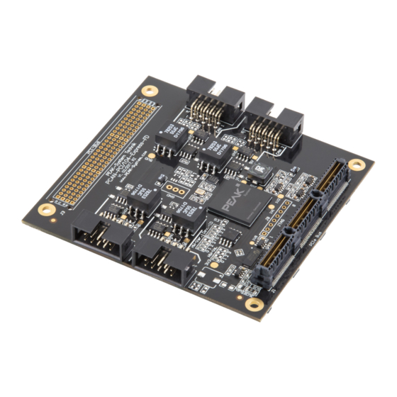
- Page 2 PCAN-PCI/104-Express FD Four Channel Four CAN channels IPEH-004082 The cover picture shows the product PCAN-PCI/104-Express FD Four Channel. Other product models have an identical form factor but vary in equipment. On request you can get the product versions with stack-through connectors for the PCI bus.
-
Page 3: Table Of Contents
PCAN-PCI/104-Express FD – User Manual Contents Introduction Properties at a Glance System Requirements Scope of Supply Installing the Software and the Card Connecting a CAN Bus Connection over D-Sub Connector Slot Bracket(s) with D-Sub Connector(s) Voltage Supply of External Devices... - Page 4 PCAN-PCI/104-Express FD – User Manual Technical Specifications Appendix A CE Certificate Appendix B Dimension Drawing Appendix C Quick Reference...
-
Page 5: Introduction
PCAN-PCI/104-Express FD – User Manual Introduction The PCAN-PCI/104-Express FD allows the connection of PCI/104- Express systems to CAN and CAN FD buses. The PCI/104-Express specification establishes PCI Express for the PC/104 form factor wherewith up to four cards can be stacked. Based on this, standardized modular embedded systems such as industrial PCs can be realized. -
Page 6: Properties At A Glance
PCAN-PCI/104-Express FD – User Manual Properties at a Glance PCI/104-Express card, 1 lane (x1) Form factor PC/104 Up to four cards can be used in one system 1, 2, or 4 High-speed CAN channels (ISO 11898-2) Complies with CAN specifications 2.0 A/B and FD CAN FD support for ISO and Non-ISO standards switchable CAN FD bit rates for the data field (64 bytes max.) -
Page 7: System Requirements
PC/104 stack with PCIe/104 connectivity to the host Windows 10, 8.1, 7 (32/64-bit) or Linux (32/64-bit) Scope of Supply PCAN-PCI/104-Express FD card, 1 Lane (x1) Slot bracket with D-Sub connector(s) for the CAN bus (two for the four-channel version) Device drivers for Windows 10, 8.1, 7 and Linux (32/64-bit) -
Page 8: Installing The Software And The Card
PCAN-PCI/104-Express FD – User Manual Installing the Software and the Card This chapter covers the software setup for the PCAN-PCI/104-Express FD card in Windows and the installation of the card in the PC/104 stack. Install the driver before you insert the card. - Page 9 Do the following to check the operational readiness: Open the Windows Start menu. Type peakcpl and press Enter . The information window for PEAK hardware appears. The plug-in card must be displayed in the table on the CAN Hardware tab.
-
Page 10: Connecting A Can Bus
PCAN-PCI/104-Express FD – User Manual Connecting a CAN Bus Connection over D-Sub Connector The High-speed CAN bus (ISO 11898-2) is connected to the 9-pin D-Sub connector. The pin assignment for CAN corresponds to the specification CiA® 303-1. Figure 1: Position of the sockets on the four-channel card (IPEH-004082);... - Page 11 For more information, see the next section 3.3. The pin assignment between the D-Sub port and the 10-pin connector on the PCAN-PCI/104-Express FD card is as follows: Figure 3: Numbering at the 10-pin connector on the board...
-
Page 12: Slot Bracket(S) With D-Sub Connector(S)
Figure 4: Single channel slot bracket Figure 5: Dual channel slot bracket To connect a CAN bus to the PCAN-PCI/104-Express FD card, use the supplied slot bracket(s). After you have connected the flat- ribbon cables from the slot bracket(s) with the 10-pin sockets, you... -
Page 13: Voltage Supply Of External Devices
External devices with low power consumption (e.g. bus converters) can be directly supplied via the CAN connector. With a solder bridge per CAN channel on the PCAN-PCI/104-Express FD board, a 5-Volt supply can optionally be routed to pin 1 of the D-Sub connector. - Page 14 PCAN-PCI/104-Express FD – User Manual Figure 6: Position of the solder fields on the top side of the four-channel card (IPEH-004082) for a 5-Volt supply; dual channel card (IPEH-004081) only CAN 1 and CAN 2; single channel card (IPEH-004080) only CAN 1...
-
Page 15: Activating The Daisy Chain
PCAN-PCI/104-Express FD – User Manual Activating the Daisy Chain The daisy chain can be activated via solder jumpers on the board to connect a CAN FD optimized connection to an existing CAN bus. This makes interference-free operation possible at higher CAN FD bit rates, because stubs and Y distributions are largely avoided. - Page 16 PCAN-PCI/104-Express FD – User Manual Assignment Assignment D-Sub CAN-H daisy chain not connected not connected not connected not connected Do the following to activate the daisy chain: Risk of short circuit! Solder with great care to avoid unwanted short circuits on the card.
- Page 17 PCAN-PCI/104-Express FD – User Manual Figure 9: Position of the solder fields on the top side of the card (IPEH-004082) for the activation of the daisy chain dual channel card (IPEH-004081) only CAN 1 and CAN 2; single channel card (IPEH-004080) only CAN 1...
-
Page 18: Activating The Internal Termination
Activating the Internal Termination The internal termination can be activated by solder jumpers on the PCAN-PCI/104-Express FD board, to terminate one end of the CAN bus with 120 Ohms. At delivery the termination is not activated. A High-speed CAN bus (ISO 11898-2) must be terminated on both ends with 120 Ohms. - Page 19 PCAN-PCI/104-Express FD – User Manual Figure 10: Position of the solder fields on the top side of the four-channel card (IPEH-004082) for the internal termination; dual channel card (IPEH-004081) only CAN 1 and CAN 2; single channel card (IPEH-004080) only CAN 1...
-
Page 20: Cabling
120 ohms at both ends. The termination prevents interfering signal reflections and ensures the proper operation of the transceivers of the connected CAN nodes (CAN interfaces, control devices). The PCAN-PCI/104-Express FD card has an optional internal termination with 120 ohms. For more information, see chapter 3.5. 3.6.2... -
Page 21: Maximum Bus Length
PCAN-PCI/104-Express FD – User Manual 3.6.3 Maximum Bus Length High-speed CAN networks have bit rates up to 1 Mbit/s. The maximum bus length primarily depends on the bit rate. The following table shows different maximum possible CAN bus length with different bit rates:... -
Page 22: Software And Api
PCAN-PCI/104-Express FD – User Manual Software and API This chapter covers the provided software PCAN-View and the programming interface PCAN-Basic. Monitor Software PCAN-View PCAN-View is a simple Windows software to view, transmit and log CAN and CAN FD messages. Note: This chapter describes the use of PCAN-View with a CAN FD card. - Page 23 PCAN-PCI/104-Express FD – User Manual Do the following to start and initialize PCAN-View: Open the Windows Start menu and select PCAN-View. The Connect dialog box appears. Figure 13: Selection of the hardware and parameters Select an interface from the list.
- Page 24 PCAN-PCI/104-Express FD – User Manual Tip: Create custom bit rates by using the arrow button (). Under Filter settings, you can limit the range of CAN IDs to be received, either for standard frames (11-bit IDs) or for extended frames (29-bit IDs).
-
Page 25: Receive/Transmit Tab
PCAN-PCI/104-Express FD – User Manual 4.1.1 Receive/Transmit Tab Figure 14: Receive/Transmit Tab The Receive/Transmit tab is the main element of PCAN-View. It contains two lists, one for received messages and one for the transmit messages. The CAN data format is hexadecimal by default. - Page 26 PCAN-PCI/104-Express FD – User Manual Enable the CAN FD checkbox to define a CAN FD message with a maximum Length of 64 data bytes. Enter the ID, the data Length, and the CAN message Data. With a length of more than 8 bytes, click on and enter the data bytes into the editor.
-
Page 27: Trace Tab
PCAN-PCI/104-Express FD – User Manual 4.1.2 Trace Tab Figure 16: Trace Tab On the Trace tab, the data tracer (data logger) of PCAN-View is used for logging the communication on a CAN bus. During this process the messages are cached in the working memory of the PC. -
Page 28: Pcan-Pci/104-Express Fd Tab
PCAN-PCI/104-Express FD – User Manual 4.1.3 PCAN-PCI/104-Express FD Tab Figure 17: PCAN-PCI/104-Express FD tab The PCAN-PCI/104-Express FD tab contains some detailed information about the hardware and driver. CAN FD ISO-mode The defined in the ISO 11898-standard is not compatible with the original protocol. -
Page 29: Bus Load Tab
PCAN-PCI/104-Express FD – User Manual 4.1.4 Bus Load Tab Figure 18: Bus load tab On the Bus Load tab, the current bus load, time course, and statistical information of the CAN channel are displayed. The CAN bus load reflects the utilization of transmission capacity. -
Page 30: Error Generator Tab
PCAN-PCI/104-Express FD – User Manual 4.1.5 Error Generator Tab Figure 19: Error Generator tab Via the Error Generator tab, the communication on the CAN bus can be disturbed for testing purposes by 6 consecutive dominant bits. This is a violation of the CAN protocol on the CAN bus which must be recognized as an error by the connected CAN nodes. -
Page 31: Status Bar
PCAN-PCI/104-Express FD – User Manual Execute the destroy action with Do it. The next received or transmitted CAN frame will be destroyed at the selected bit position. The Destroy Multiple Frames area refers to a CAN ID whose frames are to be destroyed in specific intervals. -
Page 32: Linking Own Programs With Pcan-Basic Version 4 Or Higher
On the provided DVD, you can find files of the PCAN-Basic programming interface in the directory branch Develop. This API provides basic functions for linking own programs to CAN and CAN FD interfaces by PEAK-System and can be used for the following operating systems: Windows 10, 8.1, 7 (32/64-bit) Windows CE 6.x (x86/ARMv4) -
Page 33: Features Of Pcan-Basic
Use of up to 16 channels for each hardware unit (depending on the PEAK CAN interface used) Simple switching between channels of a PEAK CAN interface Driver-internal buffer for 32,768 messages per CAN channel Precision of time stamps on received messages up to 1 μs (depending on the PEAK CAN interface used) Supports PEAK-System‘s trace formats version 1.1 and 2.0... -
Page 34: Principle Description Of The Api
PCAN-PCI/104-Express FD – User Manual Extended system for debugging operations Multilingual debugging output Output language depends on operating system Debugging information can be defined individually Thread-safe API Tip: An overview of the API functions is located in the header files. You can find detailed information about the PCAN-Basic API on the provided DVD in the text and help files (file name extensions .txt and .chm). -
Page 35: Notes About The License
Notes about the License Device drivers, the interface DLL, and further files needed for linking are property of the PEAK-System Technik GmbH and may be used only in connection with a hardware component purchased from PEAK-System or one of its partners. If a CAN hardware component... - Page 36 PCAN-PCI/104-Express FD – User Manual Technical Specifications Connectors Computer PCIe/104, PCI Express x1 (1 Lane) Stack-through PCI/104-Bus, equipped with contact strip on request D-Sub (m), 9 pins Pin assignment according to specification CiA® 303-1 Protocols CAN FD ISO 11898-1:2015, CAN FD non-ISO, CAN 2.0 A/B...
- Page 37 PCAN-PCI/104-Express FD – User Manual Measures Size 90.2 x 95.9 mm (W x L) See also dimension drawing in Appendix B on page 39 Weight Single Channel: 44 g Dual Channel: 50 g Four Channel: 56 g Conformity Directive 2014/30/EU...
- Page 38 PCAN-PCI/104-Express FD – User Manual Appendix A CE Certificate...
- Page 39 PCAN-PCI/104-Express FD – User Manual Appendix B Dimension Drawing Figure 22: Dimension drawing PCAN-PCI/104-Express FD The figure does not show the actual size of the product.
- Page 40 Check the operational readiness. Open the Windows Start menu. Type peakcpl and press Enter . An information window for PEAK Hardware opens. The plug-in card must be displayed in the table on the CAN Hardware tab. Getting Started under Windows Run the CAN monitor PCAN-View from the Windows Start menu as a sample application for accessing the card.
Need help?
Do you have a question about the PCAN-PCI/104-Express FD and is the answer not in the manual?
Questions and answers