Advertisement
Quick Links
Advertisement

Related Manuals for Peak PCAN-USB Pro


Summary of Contents for Peak PCAN-USB Pro
- Page 1 PCAN-USB Pro High-speed USB 2.0 to CAN/LIN Interface User Manual V2.1.4...
- Page 2 PCAN-USB Pro – User Manual Product Name Model Part number PCAN-USB Pro IPEH-002061 CANopen® and CiA® are registered community trade marks of CAN in Automation e.V. All other product names mentioned in this document may be the trademarks or registered trademarks of their respective companies. They are not explicitly marked by “™”...
- Page 3 PCAN-USB Pro – User Manual Properties at a Glance System Requirements Scope of Supply D-Sub Connector CAN D-Sub Connector LIN Supplying External Devices via the D-Sub Connector Cabling 3.4.1 Termination 3.4.2 Example of a Connection 3.4.3 Maximum Bus Length Status LEDs...
- Page 4 PCAN-USB Pro – User Manual 5.2.1 Receive/Transmit or Receive/Publisher 5.2.2 Trace Tab 5.2.3 Status Bar Linking Own Programs with PCAN-Basic 5.3.1 Features of PCAN-Basic 5.3.2 Principle Description of the API 5.3.3 Notes about the License Linking Own Programs with the PLIN-API...
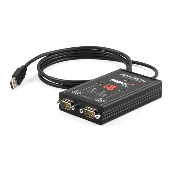
- Page 5 PCAN-USB Pro – User Manual The PCAN-USB Pro adapter enables simple connection of a PC to CAN and LIN networks. Two field busses can be connected at the same time, with up to four connections available using appropriate adapter cables (2x CAN, 2x LIN). Its robust aluminium casing makes the PCAN-USB Pro adapter suitable for mobile applications.
- Page 6 PCAN-USB Pro – User Manual Measurements of bus load including error frames and overload frames Induced error generation for incoming and outgoing CAN messages Bit rates of 1 - 20 kbit/s AMIS-30600 LIN transceiver Both LIN channels (common Ground) are opto-decoupled...
- Page 7 Manual in PDF format Note: Since the application possibilities of the PCAN-USB Pro adapter are various, special cable adapters for connecting the CAN and LIN busses are not provided. Therefore you need a 9- pin D-Sub female connector for your appliances to be connected individually.
- Page 8 PCAN-USB Pro – User Manual This chapter covers the software setup for the PCAN-USB Pro adapter under Windows and the connection of the adapter to a computer. Setup the drivers before connecting the PCAN-USB Pro adapter to the computer for the first time.
- Page 9 PCAN-USB Pro – User Manual Do the following to connect the PCAN-USB Pro adapter to the computer and complete the initialization: Note: Do not use a USB extension cable to connect the PCAN- USB Pro adapter to the computer. The use of an extension cable does not comply with the USB specification and can lead to malfunction of the adapter.
- Page 10 PCAN-USB Pro – User Manual Both D-Sub connectors on the PCAN-USB Pro adapter are each used for connecting one CAN and one LIN bus. The pin assignment is identical for both D-Sub connectors. Note: Since the application possibilities of the PCAN-USB Pro adapter are various, special cable adapters for connecting the CAN and LIN busses are not provided.
- Page 11 USB and CAN. The LIN connections are not galvanically isolated against each other. On the PCB of the PCAN-USB Pro adapter (casing opened) a 5-Volt supply can optionally be routed to pin 1 of each D-Sub connector. At delivery this pin is not assigned.
- Page 12 PCB out of the lower part of the casing. Set the solder bridge(s) on the PCB of the PCAN-USB Pro adapter according to the desired function. During this procedure take espe- cially care not to produce unwanted short circuits on the board.
- Page 13 The PCAN-USB Pro adapter does not have an internal termination. Use the adapter on a terminated CAN bus. Figure 5: Simple CAN connection In this example, the PCAN-USB Pro adapter is connected with a control unit by a cable that is terminated at both ends.
- Page 14 PCAN-USB Pro – User Manual High-Speed-CAN networks may have bit rates of up to 1 Mbit/s. The maximum bus length depends primarily on the bit rate. The following table shows the maximum possible CAN bus length at different bit rates:...
- Page 15 PCAN-USB Pro – User Manual For indication of operating conditions the PCAN-USB Pro adapter has several LEDs. Figure 6: Layout of the LEDs on the casing Status Meaning Green A High-speed USB connection (USB 2.0) with a computer is established.
- Page 16 Data is transmitted via the connected LIN bus. Under Windows the icon for removing hardware safely is not used with the PCAN-USB Pro adapter. You may unplug the adapter from the computer without any preparation. You can operate several PCAN-USB Pro adapters on a single computer at the same time.
- Page 17 CAN messages. Figure 7: PCAN-View for Windows Do the following to start and initialize PCAN-View: If PCAN-View is already installed on the hard disk, open the Windows Start menu, go to All Programs > PCAN-USB Pro, and select the entry PCAN-View.
- Page 18 PCAN-USB Pro – User Manual If you haven't installed PCAN-View together with the device driver, you can start the program directly from the supplied DVD. In the navigation program (Intro.exe) go to English > Tools, and under PCAN-View for Windows select the link Start.
- Page 19 PCAN-USB Pro – User Manual Figure 9: Receive/Transmit tab The Receive/Transmit tab is the main element of PCAN-View. It contains two lists, one for received messages and one for the transmit messages. Representation of CAN data is in hexadecimal format.
- Page 20 PCAN-USB Pro – User Manual Figure 10: Dialog box New transmit message 12. Enter the ID and the data for the new CAN message. 13. The field Cycle Time indicates if the message shall be transmitted manually or periodically. If you want to transmit the message periodically, you must enter a value greater than 0.
- Page 21 PCAN-USB Pro – User Manual Figure 11: Trace tab On the Trace tab the data tracer of PCAN-View is used for logging the communication on a CAN bus. During this process the CAN messages are cached in the working memory of the PC. Afterwards they can be saved to a file.
- Page 22 PCAN-USB Pro – User Manual Figure 12: PCAN-USB Pro tab With the PCAN-USB Pro tab you can assign a device ID to the adap- ter. Then it can be clearly identified during operation of several PCAN-USB Pro adapters on a single computer.
- Page 23 PCAN-USB Pro – User Manual Figure 13: Bus Load tab On the Bus Load tab the current bus load of the connected CAN channel and its course over time are displayed along with statistical information. The bus load of a CAN bus reflects the utilization of transmission capacity.
- Page 24 PCAN-USB Pro – User Manual Figure 14: Error Generator tab The Error Generator tab can be used to generate error frames on the connected CAN bus. In the area Destroy Single Frame you can destroy single CAN frames on the CAN bus.
- Page 25 PCAN-USB Pro – User Manual Do the following to destroy Multiple Frames: Enter the CAN ID of the frame to be destroyed. 18. Enter the Bit-Position where in the CAN frame the error shall be generated. 19. The field Number of Frames to ignore specifies the number of CAN frames that are ignored before a frame is destroyed.
- Page 26 PCAN-USB Pro – User Manual PLIN-View for Windows is a simple LIN monitor for receiving and transmitting LIN messages. Figure 16: PLIN-View Pro for Windows Note: PLIN-View Pro is provided exclusively for the use with the PCAN-USB Pro. Do the following to start and initialize PLIN-View Pro: Start the program PLIN-View Pro from the Windows Start Menu All Programs >...
- Page 27 PCAN-USB Pro – User Manual Figure 17: Selection of the LIN specific hardware and parameters 22. From the Hardware list, select the LIN channel to be used. 23. From the dropdown list Mode, select the operation mode Master or Slave to be used for the LIN channel.
- Page 28 If the Master requests data from a Slave, he can publish it in the LIN frame. In the Global Frame Table all defined LIN frame en- tries are stored that can be set with the PCAN-USB Pro. To transmit a LIN frame you have to adjust the underlying frame definition in the properties.
- Page 29 PCAN-USB Pro – User Manual 27. Change the property Checksum Type to Enhanced or Classic. 28. Change the property Direction in Publisher. 29. Select the menu command Transmit > New Frame (alternatively The dialog box New frame is shown. Figure 19: Dialog box New frame 30.
- Page 30 PCAN-USB Pro – User Manual Tip: You can use PLIN projects to simplify the work with the Global Frame Table, the Transmit or Publisher list, the Schedule tables, and the LDF files. With the menu command File > Save all files and configurations are saved in such a project for later use.
- Page 31 PCAN-USB Pro – User Manual On the upper part of the tracer is a line that issues various information about the tracer status: the current status of the LIN tracer, the complete duration that the tracer is running and recording, the number of recorded LIN frames, and the file name under which the recording will be saved.
- Page 32 On the provided DVD you can find files of the programming interface PCAN-Basic in the directory branch Develop. This API provides basic functions for linking own programs to CAN interfaces by PEAK-System and can be used for the following operating systems: Windows 7/Vista/XP (32/64-bit) Windows CE 6.x (x86/ARMv4)
- Page 33 Use of up to 8 channels for each hardware unit (depending on the PEAK CAN interface used) Simple switching between the channels of a PEAK CAN interface Driver-internal buffer for 32,768 messages per CAN channel Precision of time stamps on received messages up to 1 μs...
- Page 34 PCAN-USB Pro – User Manual The PCAN-Basic API is the interface between the user application and device driver. In Windows operating systems this is a DLL (Dynamic Link Library). The sequence of accessing the CAN interface is divided into three phases: 1.
- Page 35 Device drivers, the interface DLL, and further files needed for linking are property of the PEAK-System Technik GmbH and may be used only in connection with a hardware component purchased from PEAK-System or one of its partners. If a CAN hardware component...
- Page 36 PCAN-USB Pro – User Manual Figure 23: PLIN-API On the provided DVD you can find files to develop Windows software with an interface to a LIN bus in the directory branch Develop/PC interfaces/Windows/PLIN-API. Note: PLIN-API is provided exclusively for the use with the PCAN-USB Pro.
- Page 37 PEAK-System Technik GmbH and may be used only in connection with a hardware component purchased from PEAK-System or one of its partners. If a LIN hardware compo- nent of third-party suppliers should be compatible to one of PEAK- System, then you are not allowed to use or to pass on the driver software of PEAK-System.
- Page 38 PCAN-USB Pro – User Manual Connectors USB plug type A USB 2.0 High-Speed and USB 1.1 Full-Speed CAN/LIN D-Sub (m), 9 pins Pin assignment according to specification CiA® 102 Bit rates 1 kbit/s - 20 kbit/s Specification LIN specification 2.1 1 μs...
- Page 39 PCAN-USB Pro – User Manual Environment Operating temperature -40 - 85 °C (-40 - 185 °F) Temperature for storage -40 - 100 °C (-40 - 212 °F) and transport Relative humidity 15 - 90 %, not condensing EN 55024:2003-10 EN 55022:2008-05...
- Page 40 PCAN-USB Pro – User Manual...
- Page 41 PCAN-USB Pro – User Manual Figure 24: Top view of housing (measures in mm)
- Page 42 PCAN-USB Pro – User Manual Figure 25: Front view (measures in mm) Figure 26: Back view (measures in mm)
- Page 43 PCAN-USB Pro – User Manual Before connecting the PCAN-USB Pro adapter to the computer set up the corresponding software package from the supplied DVD (with administrator privileges). Afterwards connect the PCAN-USB Pro adapter to a USB port at your computer. The adapter is recognized by Windows and the drivers are initialized.
- Page 44 PCAN-USB Pro – User Manual Status Meaning CAN1/2 Green The CAN interface is initialized. There's a connection to a driver of the operating system. Green slow blinking A software application is connected to the CAN interface. Green quick blinking Data is transmitted via the connected CAN bus.
Need help?
Do you have a question about the PCAN-USB Pro and is the answer not in the manual?
Questions and answers