Peak PCAN-PC/104-Plus Quad User Manual
Hide thumbs
Also See for PCAN-PC/104-Plus Quad:
- User manual (35 pages) ,
- User manual (34 pages) ,
- User manual (22 pages)
Advertisement
Quick Links
Advertisement

Subscribe to Our Youtube Channel
Related Manuals for Peak PCAN-PC/104-Plus Quad


Summary of Contents for Peak PCAN-PC/104-Plus Quad
- Page 1 PCAN-PC/104-Plus Quad Four-Channel CAN Interface for PC/104-Plus User Manual V1.0.1...
- Page 2 PCAN-PC/104-Plus Quad – User Manual Product Name Model Part Number PCAN-PC/104-Plus Quad Four CAN channels IPEH-002099 On request you can get the card with stack-through connectors for the ISA bus. CANopen® and CiA® are registered community trade marks of CAN in Automation e.v.
- Page 3 PCAN-PC/104-Plus Quad – User Manual Properties at a Glance System Requirements Scope of Supply Configuring the Card 2.1.1 Setting the Position in the PC/104 Stack Installing the Software and the Card Notes for the ISA Bus Stack-through Connection D-Sub Connector...
- Page 4 PCAN-PC/104-Plus Quad – User Manual...
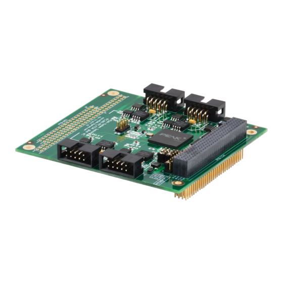
- Page 5 PCAN-PC/104-Plus Quad – User Manual The PCAN-PC/104-Plus Quad card enables the connection of four CAN networks to a PC/104-Plus system. Up to four cards can be operated, with each piggy-backing on the next. The CAN bus is connected using a 9-pin D-Sub plug on the slot brackets supplied.
- Page 6 PCAN-PC/104-Plus Quad – User Manual 5-Volts supply to the CAN connection can be connected through a solder jumper, e.g. for external bus converter 4 High-speed CAN channels (ISO 11898-2) Galvanic isolation on the CAN connection up to 500 V, separate for each CAN channel Extended operating temperature range from -40 to 85 °C...
- Page 7 PCAN-PC/104-Plus Quad – User Manual PCAN-PC/104-Plus Quad card Two Slot brackets with D-Sub connectors for the CAN bus Device drivers for Windows 7/Vista/XP (32/64-bit) and Linux (32/64-bit) PCAN-View CAN monitor for Windows PCAN-Basic programming interface consisting of an interface DLL, examples, and header files for all common programming...
- Page 8 PCAN-PC/104-Plus Quad card. Take precautions to avoid ESD when handling the card. The PCAN-PC/104-Plus Quad card must be adjusted to a specific position in the stack by setting the appropriate jumpers. The position number results from the distance to the host.
- Page 9 PCAN-PC/104-Plus Quad – User Manual Figure 1: Jumper fields IDx, CLKx, and INTx on the PCAN-PC/104-Plus Quad card Position in the PC/104 stack in relation to the host Jumper Signal ID Select CLKx Clock Select INTx Interrupt Select Because the PCI bus master operation is not used by the card, the...
- Page 10 PCAN-PC/104-Plus Quad – User Manual Setup the driver before installing the PCAN-PC/104-Plus Quad card in the PC/104 stack. Do the following to setup the driver: Make sure that you are logged in as user with administrator privileges (not needed for normal use of the card later on).
- Page 11 PCAN-PC/104-Plus Quad – User Manual Do the following to install the card into the PC/104 stack: Plug a cable from the slot bracket to a 10-pin socket for each CAN connection. Figure 2: Position of the sockets for the CAN connection,...
- Page 12 ISA bus, the connections J1 and J2 must be equipped with stack-through connectors. On request you get a respective version of the PCAN-PC/104-Plus Quad card. Taking the host as point of view, PC/104 modules with ISA bus must be plugged onto the stack behind any module with PCI bus.
- Page 13 PCAN-PC/104-Plus Quad – User Manual A High-speed CAN bus (ISO 11898-2) is connected to the 9-pin D-Sub connector. The pin assignment for CAN corresponds to the specification CiA® 102. Figure 3: Pin assignment High-speed CAN bus (view onto a D-Sub connector of the slot bracket) With the pins 1 and 9 devices with low power consumption (e.g.
- Page 14 +5 V (optional) not connected not connected Tip: You can connect a CAN bus with a different transmission standard via a bus converter. PEAK-System offers different bus converter modules (e.g. PCAN-TJA1054 for a Low-speed CAN bus according to ISO 11898-3).
- Page 15 DC/DC converter the current output is limited to 100 mA. Proceed as follows to activate the 5-Volt supply: Set the solder bridges on the PCAN-PC/104-Plus Quad card according to the desired settings. During this procedure take especially care not to produce unwanted short circuits on the card.
- Page 16 Attention! Risk of short circuit! If the option described in this section is activated, you may only connect or disconnect CAN cables or peripheral systems (e.g. bus converters) to or from the PCAN-PC/104-Plus Quad card while the computer is de- energized.
- Page 17 CAN nodes (CAN- interface, control unit) will not work. The PCAN-PC/104-Plus Quad card does not have an internal termi- nation. Use the card on a terminated CAN bus. Figure 6: Simple CAN connection In this example, the PCAN-PC/104-Plus Quad card is connected with a control unit by a cable that is terminated at both ends.
- Page 18 PCAN-PC/104-Plus Quad – User Manual High-Speed-CAN networks may have bit rates of up to 1 Mbit/s. The maximum bus length depends primarily on the bit rate. The following table shows the maximum possible CAN bus length at different bit rates:...
- Page 19 PCAN-PC/104-Plus Quad – User Manual This chapter covers the provided software PCAN-View and the programming interface PCAN-Basic. PCAN-View for Windows is a simple CAN monitor for viewing, transmitting, and logging CAN messages. Figure 7: PCAN-View for Windows Do the following to start and initialize PCAN-View: If PCAN-View is already installed on the hard disk, open the Windows Start menu, go to Programs >...
- Page 20 PCAN-PC/104-Plus Quad – User Manual If you haven’t installed PCAN-View together with the device driver, you can start the program directly from the supplied DVD. In the DVD navigation program (Intro.exe), go to English > Tools, and under PCAN-View for Windows select the link Start.
- Page 21 PCAN-PC/104-Plus Quad – User Manual Figure 9: Receive/Transmit tab The Receive/Transmit tab is the main element of PCAN-View. It contains two lists, one for received messages and one for the transmit messages. Representation of CAN data is in hexadecimal format.
- Page 22 PCAN-PC/104-Plus Quad – User Manual Figure 10: Dialog box New transmit message Enter the ID and the data for the new CAN message. The field Cycle Time indicates if the message shall be transmitted manually or periodically. If you want to transmit the message periodically, you must enter a value greater than 0.
- Page 23 PCAN-PC/104-Plus Quad – User Manual Figure 11: Trace tab On the Trace tab the data tracer of PCAN-View is used for logging the communication on a CAN bus. During this process the CAN messages are cached in the working memory of the PC. Afterwards they can be saved to a file.
- Page 24 PCAN-PC/104-Plus Quad – User Manual Figure 12: Example for the status bar The status bar shows information about the current CAN connection, about error counters (Overruns, QXmtFull), and shows error messages. You can find further information about the use of PCAN-View in the help which you can invoke in the program via the menu Help or the F1 key.
- Page 25 On the provided DVD you can find files of the programming interface PCAN-Basic in the directory branch Develop. This API provides basic functions for linking own programs to CAN interfaces by PEAK-System and can be used for the following operating systems: Windows 7/Vista/XP (32/64-bit) Windows CE 6.x (x86/ARMv4)
- Page 26 Use of up to 8 channels for each hardware unit (depending on the PEAK CAN interface used) Simple switching between channels of a PEAK CAN interface Driver-internal buffering of 32,768 messages per CAN channel Precision of time stamps on received messages up to 1 μs...
- Page 27 PCAN-PC/104-Plus Quad – User Manual The PCAN-Basic API is the interface between the user application and device driver. In Windows operating systems this is a DLL (Dynamic Link Library). The sequence of accessing the CAN interface is divided into three phases: 1.
- Page 28 “Free” and is available to other applications. Device drivers, the interface DLL, and further files needed for linking are property of the PEAK-System Technik GmbH and may be used only in connection with a hardware component purchased from PEAK-System or one of its partners. If a CAN hardware component...
- Page 29 PCAN-PC/104-Plus Quad – User Manual Connectors PC/104-Plus PCI bus (PC/104-Plus Version 2), 120-pin strip, for 5-Volt systems ISA bus: optionally equipped stack-through connectors for the ISA signals 4 High-speed CAN D-Sub (m), 9 pins Pin assignment according to specification CiA® 102 Specification ISO 11898-2;...
- Page 30 PCAN-PC/104-Plus Quad – User Manual Environment Operating temperature -40 – +85 °C (-40 – +185 °F) Temperature for storage -40 – +125 °C (-40 – +257 °F) and transport Relative humidity 15 – 90 %, not condensing EN 55024:2003-10 EN 55022:2008-05...
- Page 31 PCAN-PC/104-Plus Quad – User Manual...
- Page 32 PCAN-PC/104-Plus Quad – User Manual Figure 14: Dimension drawing PCAN-PC/104-Plus Quad. The figure doesn't show the actual size of the product.
- Page 33 Clock Select INTx Interrupt Select Before installing the PCAN-PC/104-Plus Quad card in the PC/104 stack, setup the corresponding software package from the supplied DVD (with Administrator privileges). The card is recognized by Windows and the driver is initialized. After the installation process is finished successfully you can find the entry “PCAN-PC/104-Plus”...
Need help?
Do you have a question about the PCAN-PC/104-Plus Quad and is the answer not in the manual?
Questions and answers