
Subscribe to Our Youtube Channel
Related Manuals for Peak PCAN-Dongle


Summary of Contents for Peak PCAN-Dongle
- Page 1 PCAN-Dongle Parallel Port to CAN Interface User Manual Document version 2.1.0 (2017-02-09)
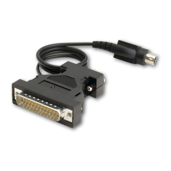
- Page 2 PCAN-Dongle opto-decoupled PS/2 IPEH-002020 The cover picture shows the PCAN-Dongle opto-decoupled. The other models have a case with silver-colored coating. PCAN® is a registered trademark of PEAK-System Technik GmbH. CANopen® and CiA® are registered community trade marks of CAN in Automation e.V.
-
Page 3: Table Of Contents
PCAN-Dongle – User Manual Contents Introduction Properties at a Glance System Requirements Scope of Supply Software and Hardware Installation Connecting a CAN Bus Connection over D-Sub connector Voltage Supply for External Devices Cabling Operation Prerequisites for the Operation Interface Information... -
Page 4: Introduction
PCs and laptops. Depending on the parallel interface present, it can be operated in "Multiplex" or "Enhanced Parallel Port" mode. Power is supplied to the PCAN-Dongle through a special adapter connected to the PC's keyboard output. The opto-decoupled version also guarantees galvanic isolation of up to 500 Volts between the PC and the CAN sides. -
Page 5: System Requirements
(only opto-decoupled model) Operating temperature range from 0 to 60 °C (32 to 140 °F) Note: This manual describes the use of the PCAN-Dongle with Windows. You can find device drivers for Linux and the corresponding information on PEAK-System's website under www.peak-system.com/linux. -
Page 6: Scope Of Supply
PCAN-Dongle – User Manual Scope of Supply PCAN-Dongle in plastic casing Device drivers for Windows 10, 8.1, 7 (32-bit) and Linux (32/64-bit) CAN monitor PCAN-View for Windows CAN monitor PCAN-View for DOS Programming interface PCAN-Basic for developing applications with CAN connection... -
Page 7: Software And Hardware Installation
PCAN-Dongle – User Manual Software and Hardware Installation This chapter covers the software setup for the PCAN-Dongle under Windows. Install the driver before you install the adapter. Do the following to install the driver: Start Intro.exe from the supplied DVD. - Page 8 Pull the keyboard connector from the corresponding port at the computer. Connect the T-piece at the cable of the PCAN-Dongle to the keyboard port. Reconnect the keyboard to the free end of the T-piece.
- Page 9 PCAN-Dongle – User Manual Do the following to install the adapter: After turning on the computer, the LED at the PCAN-Dongle must light red. This indicates that the power supply for the PCAN-Dongle is correct. Attention! Don't remove PCAN-Dongle from the computer while powered on (red LED on PCAN-Dongle is lit).
-
Page 10: Connecting A Can Bus
9 are not in use at the delivery state. For more information see the next section 3.2. Tip: You can connect a CAN bus with a different transmission standard via a bus converter. PEAK-System offers different bus converter modules (e.g. PCAN-TJA1054 for a Low-speed CAN bus according to ISO 11898-3). -
Page 11: Voltage Supply For External Devices
External devices with low power consumption (e.g. bus converters) can be directly supplied via the CAN connector. With a solder bridge on the PCAN-Dongle board (casing opened), a 5-Volt supply can optionally be routed to pin 1 and/or pin 9 of the D-Sub connector (PCAN-Dongle opto-decopled: pin 1 only). - Page 12 Figure 3: PCAN-Dongle (bottom view) 5-Volt supply D-Sub connector Solder field Without Pin 1 Pin 9 Pin 1 and (Standard) pin 9 CAN 1 Figure 4: PCAN-Dongle opto-decoupled (top view) 5-Volt supply D-Sub connector Solder field Without Pin 1 (Standard) CAN 1...
-
Page 13: Cabling
120 ohms at both ends. The termination prevents interfering signal reflections and ensures the proper operation of the transceivers of the connected CAN nodes (CAN interfaces, control devices). The PCAN-Dongle adapter does not have an internal termination. Use the adapter on a terminated bus. 3.3.2... - Page 14 PCAN-Dongle – User Manual 3.3.3 Maximum Bus Length High-speed CAN networks have bit rates up to 1 Mbit/s. The maximum bus length primarily depends on the bit rate. The following table shows different maximum possible CAN bus length with different bit rates:...
-
Page 15: Operation
PCAN-Dongle – User Manual Operation Prerequisites for the Operation Under Windows you must explicitly determine the use of an interrupt for the parallel interface. This is done in the Windows Device Manager. Do the following to assign an interrupt to the parallel interface under Windows: Open the Windows Device Manager. -
Page 16: Interface Information
PCAN-Dongle – User Manual Figure 7: Indicating the use of an interrupt Interface Information For the initialization of the PCAN-Dongle during the start of an application you need information about the used interrupt and port address of the parallel interface. - Page 17 PCAN-Dongle – User Manual Select the tab Resources. From the entries I/O Range (first value = port address) and Interrupt or IRQ in the list you can see the needed information. Write down this information for later use. Figure 9: Resource information about the parallel interface...
-
Page 18: Operating Modes
PCAN-Dongle – User Manual Operating Modes The PCAN-Dongle can be used in one of four possible operating modes: Name of operating Alternative Description mode identifier Multiplex Mode PEAK Dongle-CAN Standard Parallel Port (SPP) EPP Mode PEAK Dongle-CAN Extended Capability Port (ECP) -
Page 19: Software And Api
PCAN-Dongle – User Manual Software and API This chapter covers the provided software PCAN-View and the programming interface PCAN-Basic. Monitor Software PCAN-View PCAN-View is simple Windows software for viewing, transmitting, and logging CAN and CAN FD messages. Note: This chapter describes the use of PCAN-View with a CAN adapter. - Page 20 Add CAN hardware appears. If the mode of the parallel interface is set to ECP in the computer's BIOS setup, you can register the PCAN-Dongle as PEAK Dongle-CAN SJA EPP. Enter the port address and the interrupt of the used parallel...
- Page 21 PCAN-Dongle – User Manual Figure 12: Selection of a hardware type Confirm your input with OK. From the drop-down list, select the Bit rate that is used by all nodes on the CAN bus. Tip: You can create custom bit rates by using the button ().
- Page 22 PCAN-Dongle – User Manual 5.1.1 Receive/Transmit Tab Figure 13: Receive/Transmit Tab The Receive/Transmit tab is the main element of PCAN-View. It contains two lists, one for received messages and one for the transmit messages. The CAN data format is hexadecimal by default.
- Page 23 PCAN-Dongle – User Manual Enter the ID, the data Length, and the CAN message Data. Note: With the program version 4 of PCAN-View, the DLC field was renamed to Length. Latter reflects the actual data length. Enter a value into the Cycle Time field to choose manually or periodically message transmission.
- Page 24 PCAN-Dongle – User Manual 5.1.2 Trace Tab Figure 15: Trace Tab On the Trace tab, the data tracer (data logger) of PCAN-View is used for logging the communication on a CAN bus. During this process the messages are cached in the working memory of the PC.
- Page 25 PCAN-Dongle – User Manual 5.1.3 PCAN-Dongle Figure 16: PCAN-Dongle The PCAN-Dongle tab contains some detailed information about the hardware and driver. 5.1.4 Status Bar Figure 17: Display of the Status Bar The status bar shows information about the current CAN connection, about error counters (Overruns, QXmtFull) and shows error messages.
-
Page 26: Linking Own Programs With Pcan-Basic
On the provided DVD, you can find files of the PCAN-Basic programming interface in the directory branch Develop. This API provides basic functions for linking own programs to CAN and CAN FD interfaces by PEAK-System and can be used for the following operating systems: Windows 10, 8.1, 7 (32/64-bit) Windows CE 6.x (x86/ARMv4) - Page 27 Use of up to 16 channels for each hardware unit (depending on the PEAK CAN interface used) Simple switching between the channels of a PEAK CAN interface Driver-internal buffer for 32,768 messages per CAN channel Precision of time stamps on received messages up to 1 μs (depending on the PEAK CAN interface used) Supports PEAK-System‘s trace formats version 1.1 and 2.0 (for...
- Page 28 PCAN-Dongle – User Manual Extended system for debugging operations Multilingual debugging output Output language depends on operating systems Debugging information can be defined individually Tip: An overview of the API functions is located in the header files. You can find detailed information about the PCAN-Basic API on the provided DVD in the text and help files (file name extensions .txt and .chm).
- Page 29 Notes about the License Device drivers, the interface DLL, and further files needed for linking are property of the PEAK-System Technik GmbH and may be used only in connection with a hardware component purchased from PEAK-System or one of its partners. If a CAN hardware component...
-
Page 30: Frequently Asked Questions (Faq)
EPP mode. Is this in the nineties. Only the EPP correct? extension existed during the time, when the PCAN-Dongle arose. With version 1.9 the EPP extension already had similarities to the ECP extension, which is usually used in computers today. -
Page 31: Technical Specifications
Galvanic isolation up to 500 V (only for IPEH-002020) Supplying external PCAN-Dongle: D-Sub pin1/9; 5 V, max. 100mA devices PCAN-Dongle opto: D-Sub pin 1; 5 V, max. 50mA via solder bridge(s), not assigned at delivery Supply Supply voltage +5 V DC... - Page 32 PCAN-Dongle – User Manual Conformity Directive 2014/30/EU DIN EN 55024:2016-05 DIN EN 55032:2016-02 RoHS 2 Directive 2011/65/EU DIN EN 50581 VDE 0042-12:2013-02...
-
Page 33: Appendix Ace Certificate
PCAN-Dongle – User Manual Appendix A CE Certificate... -
Page 34: Appendix B Quick Reference
Hardware Installation Install the driver from the supplied DVD, before you connect the PCAN-Dongle to the computer's parallel port. Insert the T-piece at the cable's end between the keyboard port at the computer and the keyboard connector (for power supply). The LED must light red.
Need help?
Do you have a question about the PCAN-Dongle and is the answer not in the manual?
Questions and answers