Table of Contents
Advertisement
Quick Links
Download this manual
See also:
User Manual
Advertisement
Table of Contents

Related Manuals for Peak PCAN-ISA


Summary of Contents for Peak PCAN-ISA
- Page 1 PCAN-ISA CAN Interface for ISA User Manual...
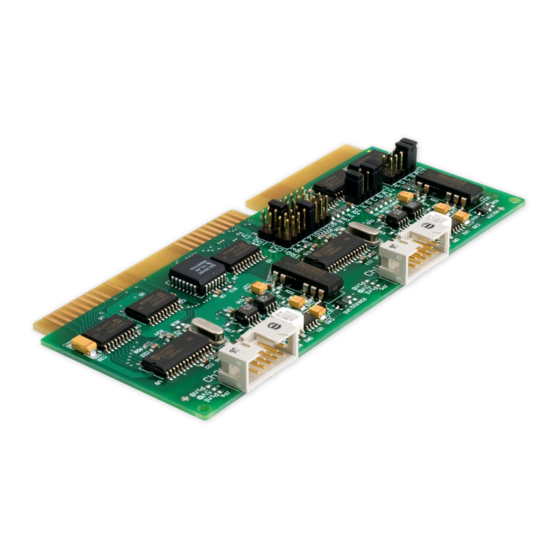
- Page 2 IPEH-002077 opto-decoupled isolation for CAN connections The cover picture shows the product PCAN-ISA Dual Channel opto-decoupled. Other product versions have an identical form factor but vary in equipment. Product names mentioned in this manual may be the trademarks or registered trademarks of their respective companies.
-
Page 3: Table Of Contents
PCAN-ISA – User Manual Contents Introduction Properties at a Glance System Requirements Scope of Supply Hardware Installation Configuring the PCAN-ISA Card Installation into the Computer Modifying the Computer's BIOS Settings 2.3.1 Indicating Used Interrupts 2.3.2 Deactivating the APIC Mode Connecting a CAN Bus... -
Page 4: Introduction
Quick Reference with brief information about the installation and operation of the PCAN-ISA card. With the PCAN-ISA add-on card for the ISA bus in the computer you can connect one or with the Dual Channel version even two CAN busses. Thus the computer becomes part of a High-speed CAN network (HS-CAN). -
Page 5: System Requirements
Support for operating systems Windows (starting with 2000) and Linux Note: This manual describes the use of the PCAN-ISA card with Windows. You can find device drivers for Linux and the corresponding information on PEAK-System's website under www.peak-system.com/linux. -
Page 6: Scope Of Supply
Scope of Supply The scope of supply normally consists of the following parts: PCAN-ISA card Slot bracket with one or two CAN D-Sub connectors including cables to the PCAN-ISA card CD-ROM with software (drivers, utilities), programming exam- ples, and documentation... -
Page 7: Hardware Installation
Hardware Installation Configuring the PCAN-ISA Card Before you install the PCAN-ISA card into the computer you may need to configure it. For each CAN channel an interrupt (IRQ) and an I/O address range is set for operation in the computer. - Page 8 PCAN-ISA – User Manual Figure 1: PCAN-ISA Single Channel – Position of the jumper fields for setting the I/O address range (JP1, left marker) and the interrupt (JP3, right marker) Figure 2: PCAN-ISA Dual Channel – Position of the jumper fields for setting...
- Page 9 Interrupt An interrupt (IRQ) must be assigned to each CAN channel. The PCAN-ISA card supports the interrupts 3, 4, 5, 7, 10, 11, 12, and 15. The default setting at delivery for CAN channel 1 is interrupt 10, for CAN channel 2 interrupt 5.
-
Page 10: Installation Into The Computer
You can look up the pin assignment of the 10-pin CAN connectors on the card in section 0 on page 11. Figure 3: Connectors for the cable(s) to the slot bracket (here: PCAN-ISA Dual Channel, the single-channel version only has the left connector Ch1) Close the computer's casing. -
Page 11: Modifying The Computer's Bios Settings
PCAN-ISA – User Manual Modifying the Computer's BIOS Settings To ensure a flawless operation of the PCAN-PC/104 card it is neces- sary that you adjust settings in the BIOS setup of the computer: Indicate used interrupts Deactivate the APIC mode Note: Due to a diversity of existing BIOS setup versions for computers we cannot give detailed instructions here. -
Page 12: Deactivating The Apic Mode
PCAN-ISA – User Manual 2.3.2 Deactivating the APIC Mode Note: Do not mix up APIC with ACPI. The APIC mode is a certain type of interrupt management in a computer. If the APIC mode is active in your computer, you must deactivate it so that the PCAN-PC/104 card can work properly with interrupts. -
Page 13: Connecting A Can Bus
Figure 4: Pin assignment HS-CAN (view onto connector of the slot bracket) The pin assignment between the D-Sub port and the 10-pin connector on the PCAN-ISA card is as follows: Figure 5: Numbering at the 10-pin connector Assignment Assignment D-Sub... -
Page 14: 5-Volt Supply At The Can Connector
Therefore the current output is limited to about 50 mA. Attention! At this procedure special care is indispensable, since there is a short circuit danger. The PCAN-ISA card could be des- troyed and/or the power supply or electronics of the computer or other components connected could be damaged. - Page 15 PCAN-ISA – User Manual Figure 6: Position of the solder bridge fields for the 5-Volt supply 5-Volt supply → None Pin 1 Pin 9 Pin 1 + Pin 9 JP5 (CAN channel 1) / JP6 (CAN channel 2)
-
Page 16: Software Setup
PCAN-ISA – User Manual Software Setup Under Windows a driver is needed that can access the PCAN-ISA card and that provides the interface for Windows applications. Beside the mentioned device driver the CAN monitor PCAN-View for Windows can also set up. -
Page 17: Software
PCAN-ISA – User Manual Software This chapter deals with the provided software and the software interface to the PCAN-ISA card. PCAN-View for Windows PCAN-View for Windows is a simple CAN monitor for viewing and transmitting CAN messages. Installation You can install the application optionally during the driver setup... - Page 18 PCAN-ISA – User Manual Figure 7: Selection of the CAN specific parameters If no entry is in the list “Available CAN hardware” (for example at the first program start), you need to add one: Press the button Add. The dialog box “Add CAN hardware”...
-
Page 19: Linking Own Programs With Pcan-Light
On the supplied CD-ROM you can find files that are provided for software development. You can access them with the navigation program (button Programming). The files exclusively serve the linking of own programs to hardware by PEAK-System with the help of the installed device driver under Windows. - Page 20 PEAK-System or one of its partners. If a CAN hardware component of third party suppliers should be compatible to one of PEAK-System, then you are not allowed to use or to pass on the driver software of PEAK-System.
-
Page 21: Frequently Asked Questions (Faq)
PCAN-ISA – User Manual Frequently Asked Questions (FAQ) Question Answer Can I use several PCAN- Yes. When there's a lack of resources it is possible to share the same interrupt ISA cards in the same between CAN channels. However, computer? consider that an unique I/O address range is assigned to each CAN channel. -
Page 22: Technical Specifications
PCAN-ISA – User Manual Technical Specifications Connectors Computer ISA bus with 8 MHz clock rate, 16 bit bus width D-Sub (m), 9 pins Pin assignment according to CiA recommendation DS 102-1 Opto-decoupled versions: galvanic isolation up to 500 V (separate for each CAN channel) - Page 23 PCAN-ISA – User Manual Measures Size 143 x 66 x 13 mm (5 5/8 x 2 5/8 x 1/2 inches) Weight PCAN-ISA Single Channel: 39 g PCAN-ISA Dual Channel: 45 g PCAN-ISA Single Channel opto-dec.: 41 g PCAN-ISA Dual Channel opto-dec.:...
-
Page 24: Appendix Ace Certificate
PCAN-ISA – User Manual Appendix A CE Certificate... -
Page 25: Appendix B Quick Reference
Only on the Dual Channel version Hardware Installation / Configuring the Computer Insert the PCAN-ISA card into a free ISA slot (16 bit) of the switched off computer. After switching on the computer enter the BIOS setup. In the PnP table mark the interrupts used by the PCAN-ISA card as reserved.
Need help?
Do you have a question about the PCAN-ISA and is the answer not in the manual?
Questions and answers