
Related Manuals for Peak PCAN-USB Pro FD


Summary of Contents for Peak PCAN-USB Pro FD
-
Page 1: User Manual
PCAN-USB Pro FD CAN FD and LIN Interface for High-Speed USB 2.0 User Manual Document version 1.3.0 (2016-04-11) - Page 2 © 2016 PEAK-System Technik GmbH Duplication (copying, printing, or other forms) and the electronic distribution of this document is only allowed with explicit permission of PEAK-System Technik GmbH. PEAK-System Technik GmbH reserves the right to change technical data without prior announcement. The general business conditions and the regulations of the license agreement apply.
-
Page 3: Table Of Contents
PCAN-USB Pro FD – User Manual Contents Introduction Properties at a Glance System Requirements Scope of Supply Installing the Software and the Adapter Connecting the CAN and LIN Bus CAN Connection over D-Sub Connector LIN Connection over D-Sub Connector Voltage Supply of External Devices... - Page 4 PCAN-USB Pro FD – User Manual LIN Monitor PLIN-View Pro for Windows 5.2.1 Receive/Transmit or Receive/Publisher 5.2.2 Trace Tab 5.2.3 Status Bar Linking Own Programs with PCAN-Basic Version 4 or Higher 5.3.1 Features of PCAN-Basic 5.3.2 Principle Description of the API 5.3.3...
-
Page 5: Introduction
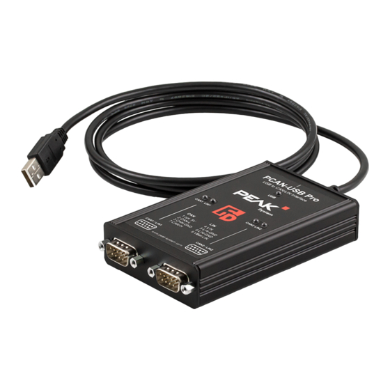
PCAN-USB Pro FD – User Manual Introduction The PCAN-USB Pro FD adapter enables the connection of CAN FD and LIN networks to a computer via USB. Two field busses can be connected at the same time, up to four with appropriate adapter cables (2 x CAN FD, 2 x LIN). -
Page 6: Properties At A Glance
PCAN-USB Pro FD – User Manual Properties at a Glance Adapter for High-speed USB 2.0 (compatible to USB 1.1 and USB 3.0) Transmitting and receiving of CAN FD and LIN messages using 2 D-Sub connections (both with pin assignment for CAN FD and LIN bus) Time stamp resolution 1 μs... -
Page 7: System Requirements
Hardware can work through a schedule table (up to 8 tables can be configured with a total of 256 slots) Note: This manual describes the use of the PCAN-USB Pro FD with Windows. You can find CAN drivers for Linux and the... -
Page 8: Scope Of Supply
PCAN-USB Pro FD – User Manual Note: Do not use a USB extension cable to connect the PCAN- USB Pro FD adapter to the computer. The use of an extension cable does not comply with the USB specification and can lead to malfunction of the adapter. -
Page 9: Installing The Software And The Adapter
PCAN-USB Pro FD – User Manual Installing the Software and the Adapter This chapter covers the software setup for the PCAN-USB Pro FD adapter under Windows and the connection of the adapter to a computer. Install the driver before you connect the adapter to the computer. -
Page 10: Connecting The Can And Lin Bus
PCAN-USB Pro FD – User Manual Connecting the CAN and LIN Both D-Sub connectors on the PCAN-USB Pro FD adapter are each used for connecting one CAN and one LIN bus. The pin assignment is identical for both D-Sub connectors. -
Page 11: Lin Connection Over D-Sub Connector
Each CAN connection separately has a galvanic isolation up to 500 V against USB and LIN. Tip: You can connect a CAN bus with a different transmission standard via a bus converter. PEAK-System offers different bus converter modules (e.g. PCAN-TJA1054 for a Low-speed CAN bus according to ISO 11898-3). -
Page 12: Voltage Supply Of External Devices
External devices with low power consumption (e.g. bus converters) can be directly supplied via the CAN connector. With a solder bridge per CAN channel on the PCAN-USB Pro FD board (casing opened), a 5-Volt supply can optionally be routed to pin 1 of the D-Sub connector. - Page 13 PCAN-USB Pro FD – User Manual Remove the two outer screws next to the D-Sub connectors at the front of the casing. Figure 5: Attachment points of the D-Sub connectors at the front side of the casing Remove the casing cover.
- Page 14 PCAN-USB Pro FD – User Manual Figure 6: Top view PCAN-USB Pro FD board, solder fields JP4/JP7 5-Volt supply D-Sub Solder Without With connector field (standard) (Pin 1) CAN1 CAN2 Risk of short circuit! The 5-Volt supply is not protected separately.
-
Page 15: Activating The Internal Can Termination
PCAN-USB Pro FD – User Manual Activating the Internal CAN Termination The termination can be activated by solder jumpers for each channel on the board. At delivery the termination is not activated. A High-speed CAN bus (ISO 11898-2) must be terminated on both ends with 120 Ohms. - Page 16 PCAN-USB Pro FD – User Manual Lift the back of the case and slide the circuit board in direction of the front over the lower part of the casing. The bottom of the circuit board is accessible now. Set the solder bridges on the circuit board of the adapter to activate the internal termination.
- Page 17 PCAN-USB Pro FD – User Manual Figure 9: Top view PCAN-USB Pro FD board, solder fields JP1/JP2 and JP5/JP6 Internal termination D-Sub Solder Without connector fields Active (standard) JP2 and CAN1 JP5 and CAN2...
-
Page 18: Cabling
3.4. 3.5.2 Example of a Connection Figure 10: Simple CAN connection In this example, the PCAN-USB Pro FD adapter is connected with a control unit by a cable that is terminated with 120 ohms at both ends. -
Page 19: Maximum Bus Length
PCAN-USB Pro FD – User Manual 3.5.3 Maximum Bus Length High-Speed-CAN networks may have bit rates of up to 1 Mbit/s. The maximum bus length depends primarily on the bit rate. The following table shows the maximum possible CAN bus length... -
Page 20: Operation
PCAN-USB Pro FD – User Manual Operation Status LEDs For indication of operating conditions the PCAN-USB Pro FD adapter has several LEDs. Figure 11: Layout of the LEDs on the casing Status Meaning Green A High-speed USB connection (USB 2.0) with a computer is established. -
Page 21: Unplugging The Usb Connection
Data is transmitted via the connected LIN bus. Unplugging the USB Connection On Windows, the icon for removing hardware safely is not used with the PCAN-USB Pro FD adapter. You may unplug the adapter from the computer without any preparation. Distinguishing Several PCAN-USB Pro FD... -
Page 22: Software And Api
PCAN-USB Pro FD – User Manual Software and API This chapter covers the provided software PCAN-View and PLIN- View Pro and the programming interfaces PCAN-Basic and the PLIN-API. Monitor Software PCAN-View PCAN-View is simple Windows software for viewing, transmitting, and logging CAN and CAN FD messages. - Page 23 PCAN-USB Pro FD – User Manual Do the following to start and initialize PCAN-View: Open the Windows Start menu and select PCAN-View. The Connect dialog box appears. Figure 13: Selection of the specific hardware and parameters Select an interface from the list.
- Page 24 PCAN-USB Pro FD – User Manual Tip: You can create custom bit rates by using the button (). Under Filter settings you can limit the range of CAN IDs to be received, either for standard frames (11-bit IDs) or for extended frames (29-bit IDs).
-
Page 25: Receive/Transmit Tab
PCAN-USB Pro FD – User Manual 5.1.1 Receive/Transmit Tab Figure 14: Receive/Transmit tab The Receive/Transmit tab is the main element of PCAN-View. It contains two lists, one for received messages and one for the transmit messages. The CAN data format is hexadecimal by default. - Page 26 PCAN-USB Pro FD – User Manual Enable the CAN FD checkbox to define a CAN FD message with a maximum Length of 64 data bytes. Enter the ID, the data Length, and the CAN message Data. With a length of more than 8 bytes, click on and enter the data bytes into the editor.
-
Page 27: Trace Tab
PCAN-USB Pro FD – User Manual 5.1.2 Trace Tab Figure 16: Trace tab On the Trace tab, the data tracer (data logger) of PCAN-View is used for logging the communication on a CAN bus. During this process the messages are cached in the working memory of the PC. -
Page 28: Pcan-Usb Pro Fd Tab
PCAN-USB Pro FD adapters on a computer at the same time. To identify a PCAN-USB Pro FD adapter, you first go to the dialog box for selecting the hardware of PCAN-View (Figure 13 on page 23). In the list “Available PCAN hardware and PCAN-nets”, you can perform a right-click on every USB adapter and execute the command "identify". -
Page 29: Bus Load Tab
PCAN-USB Pro FD – User Manual If required, the user can switch to the CAN FD protocol used in the environment with the Enable / Disable button („Non-ISO“ and „ISO“). 5.1.4 Bus Load Tab Figure 18: Bus Load tab On the Bus Load tab, the current bus load, time course, and statistical information of the CAN channel are displayed. -
Page 30: Error Generator Tab
CAN ID The Destroy Single Frame area refers to the next CAN frame that is recognized by the PCAN-USB Pro FD adapter after activation. Do the following to destroy a single CAN frame: Enter the Bit-Position where in the CAN frame the error is to be generated. -
Page 31: Status Bar
PCAN-USB Pro FD – User Manual The next received or transmitted CAN frame will be des- troyed at the selected bit position. The Destroy Multiple Frames area refers to a CAN ID whose frames are to be destroyed in specific intervals. -
Page 32: Lin Monitor Plin-View Pro For Windows
Do the following to start and initialize PLIN-View Pro: Start the program PLIN-View Pro from the Windows Start Menu All Programs > PEAK-Drivers and then PLIN-View Pro. The dialog box for selecting the LIN hardware and for setting the LIN parameters appears. - Page 33 PCAN-USB Pro FD – User Manual Figure 22: Selection of the LIN specific hardware and parameters From the Hardware list, select the LIN channel to be used. From the dropdown list Mode, select the operation mode Master or Slave to be used for the LIN channel.
-
Page 34: Receive/Transmit Or Receive/Publisher Tab
Slave, he can publish it in the LIN frame. In the Global Frame Table all defined LIN frame entries are stored that can be set with the PCAN-USB Pro FD. To transmit a LIN frame you have to adjust the underlying frame definition in the properties. - Page 35 PCAN-USB Pro FD – User Manual Do the following to transmit a LIN frame with PLIN-View Pro: Select a frame from the Global Frame Table. Change the property Checksum Type to Enhanced or Classic. Change the property Direction in Publisher.
-
Page 36: Trace Tab
PCAN-USB Pro FD – User Manual Note: You can also manage and perform Schedule Tables. Fur- thermore you can open LDF files and manage Schedule Tables with their information. The Schedule Tables are used to vali- date or edit data and to present it symbolically. -
Page 37: Status Bar
PCAN-USB Pro FD – User Manual of data is done continuously until the tracer is stopped or the storage space on the selected medium is no longer sufficient. On the upper part of the tracer is a line that issues various... -
Page 38: Linking Own Programs With Pcan-Basic Version 4 Or Higher
On the provided DVD, you can find files of the programming inter- face PCAN-Basic in the directory branch Develop. This API provides basic functions for linking own programs to CAN and CAN FD interfaces by PEAK-System and can be used for the following operating systems: Windows 10, 8.1, 7(32/64-bit) Windows CE 6.x (x86/ARMv4) -
Page 39: Features Of Pcan-Basic
Use of up to 16 channels for each hardware unit (depending on the PEAK CAN interface used) Simple switching between the channels of a PEAK CAN interface Driver-internal buffer for 32,768 messages per CAN channel Precision of time stamps on received messages up to 1 μs (depending on the PEAK CAN interface used) Supports PEAK-System‘s trace formats version 1.1 and 2.0 (for... -
Page 40: Principle Description Of The Api
PCAN-USB Pro FD – User Manual Extended system for debugging operations Multilingual debugging output Output language depends on operating systems Debugging information can be defined individually Thread-safe API Tip: An overview of the API functions is located in the header files. -
Page 41: Notes About The License
Notes about the License Device drivers, the interface DLL, and further files needed for linking are property of the PEAK-System Technik GmbH and may be used only in connection with a hardware component purchased from PEAK-System or one of its partners. If a CAN hardware component... -
Page 42: Linking Own Programs With The Plin-Api
PCAN-USB Pro FD – User Manual Linking Own Programs with the PLIN-API Figure 28: PLIN-API On the provided DVD, you can find files to develop Windows software with an interface to a LIN bus in the directory branch Develop/PC interfaces/Windows/PLIN-API. - Page 43 PEAK-System Technik GmbH and may be used only in connection with a hardware component purchased from PEAK-System or one of its partners. If a LIN hardware compo- nent of third-party suppliers should be compatible to one of PEAK- System, then you are not allowed to use or to pass on the driver software of PEAK-System.
-
Page 44: Technical Specifications
PCAN-USB Pro FD – User Manual Technical Specifications Connectors USB plug type A CAN/LIN D-Sub (m), 9 pins Pin assignment according to specification CiA® 303-1 Type High-speed USB 2.0 (compatible with USB 1.1 and USB 3.0) Specification CAN FD 1.0 (compatible with CAN 2.0) - Page 45 PCAN-USB Pro FD – User Manual Power supply Supply voltage 5 V DC via USB port LIN operation: 8 - 18 V DC via D-Sub connector Power consumption max. 200 mA at 5 V via USB Environment Operating temperature -40 - 85 °C (-40 - 185 °F) Temperature for storage -40 - 100 °C (-40 - 212 °F)
-
Page 46: Appendix Ace Certificate
PCAN-USB Pro FD – User Manual Appendix A CE Certificate... -
Page 47: Appendix B Dimension Drawing
PCAN-USB Pro FD – User Manual Appendix B Dimension Drawing Figure 29: Top view of housing The figure doesn’t show the actual size of the product. -
Page 48: Appendix C Quick Reference
Software/Hardware Installation under Windows Install the driver from the supplied DVD, before you connect the PCAN-USB Pro FD to the computer. After that, you connect the adapter to a USB port of the computer or of a connected USB hub. - Page 49 PCAN-USB Pro FD – User Manual Status Meaning CAN1/2 Green The CAN interface is initialized. There's a connection to a driver of the operating system. Green slow blinking A software application is connected to the CAN interface. Green quick blinking Data is transmitted via the connected CAN bus.
Need help?
Do you have a question about the PCAN-USB Pro FD and is the answer not in the manual?
Questions and answers