Table of Contents
Advertisement
Quick Links
Advertisement
Table of Contents

Related Manuals for Peak PCAN-ISA


Summary of Contents for Peak PCAN-ISA
-
Page 1: User Manual
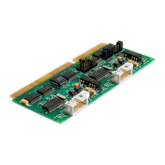
PCAN-ISA CAN Interface for ISA User Manual Document version 2.0.1 (2017-02-03) - Page 2 IPEH-002077 opto-decoupled isolation for CAN connections The cover picture shows the product PCAN-ISA Dual Channel opto-decoupled. Other product versions have an identical form factor but vary in equipment. Product names mentioned in this manual may be the trademarks or registered trademarks of their respective companies.
-
Page 3: Table Of Contents
PCAN-ISA – User Manual Contents Introduction Properties at a Glance System Requirements Scope of Supply Configuration and Installation Configuring the Card 2.1.1 Position of the Jumper Fields 2.1.2 I/O Address Range 2.1.3 Interrupt Installing the Software Installing the Hardware Modifying the Computer's BIOS Settings 2.4.1... - Page 4 PCAN-ISA – User Manual Linking Own Programs with PCAN-Basic 4.2.1 Features of PCAN-Basic 4.2.2 Principle Description of the API 4.2.3 Notes about the License Frequently Asked Questions (FAQ) Technical Specifications Appendix A CE Certificate Appendix B Quick Reference...
-
Page 5: Introduction
Device drivers exist for different operating systems, so programs can easily access a connected CAN bus. Note: This manual refers to different versions of the PCAN-ISA card. Differences at use and at the technical specifications are mentioned accordingly in this manual. -
Page 6: System Requirements
Extended operating temperature range from -40 to 85 °C (-40 to 185 °F) Note: This manual describes the use of the PCAN-ISA card with Windows. You can find device drivers for Linux and the corresponding information on PEAK-System's website under www.peak-system.com/linux. -
Page 7: Scope Of Supply
PCAN-ISA – User Manual Scope of Supply Plug-in card PCAN-ISA Slot bracket with D-Sub connectors for the CAN bus Device drivers for Windows 10, 8.1, 7 (32-bit) and Linux (32/64-bit) Device driver for Windows CE 6.x (x86 and ARMv4 processor support) -
Page 8: Configuration And Installation
Configuration and Installation Configuring the Card Before you install the PCAN-ISA card into the computer you may need to configure it. For each CAN channel an interrupt (IRQ) and an I/O address range is set for operation in the computer. -
Page 9: I/O Address Range
PCAN-ISA – User Manual Figure 1: PCAN-ISA Single Channel – Position of the jumper fields for setting the I/O address range (JP1, left marker) and the interrupt (JP3, right marker) Figure 2: PCAN-ISA Dual Channel – Position of the jumper fields for setting... -
Page 10: Interrupt
Interrupt An interrupt (IRQ) must be assigned to each CAN channel. The PCAN-ISA card supports the interrupts 3, 4, 5, 7, 10, 11, 12, and 15. The default setting at delivery for CAN channel 1 is interrupt 10, for CAN channel 2 interrupt 5. -
Page 11: Installing The Software
"Installer database of PEAK Drivers". The driver setup starts. Follow the program instructions until the Costum Setup is displayed. Figure 3: Driver selection in the PEAK-Drivers Setup Deselect the CAN device drivers and select CAN device drivers Non-Plug-and-Play (see Figure 3). -
Page 12: Installing The Hardware
64-bit Windows. Follow the further instructions. Installing the Hardware Do the following to install the PCAN-ISA card into the computer: Turn off the computer. Open the computer case and plug the PCAN-ISA card into an empty slot on the computer's motherboard. -
Page 13: Modifying The Computer's Bios Settings
PCAN-ISA – User Manual Figure 4: Connectors for the cable(s) to the slot bracket (here: PCAN-ISA Dual Channel, the Single Channel version only has the left connector Ch1) Modifying the Computer's BIOS Settings To ensure a flawless operation of the PCAN-ISA card it is necessary... -
Page 14: Deactivating The Apic Mode
PCAN-ISA – User Manual In the BIOS setup itself you can often find the settings for the interrupts under a menu item containing the text PnP. For the interrupt(s) used by PCAN-ISA change the setting to Reserved or Legacy ISA. 2.4.2 Deactivating the APIC Mode Note: Do not mix up APIC with ACPI. - Page 15 PCAN-ISA – User Manual If Windows doesn't start properly, reinstall it or perform a repair installation.
-
Page 16: Connecting A Can Bus
9 are not in use at the delivery state. For more information see the next section 3.2. Tip: You can connect a CAN bus with a different transmission standard via a bus converter. PEAK-System offers different bus converter modules (e.g. PCAN-TJA1054 for a Low-speed CAN bus according to ISO 11898-3). -
Page 17: Voltage Supply For External Devices
CAN connector (independently for each CAN connector on the Dual Channel version). With a solder bridge on the PCAN-ISA card, a 5-Volt supply can optionally be routed to pin 1 and/or pin 9 of the D-Sub connector. - Page 18 PCAN-ISA – User Manual Do the following to activate the voltage supply: Risk of short circuit! Solder with great care to avoid unwanted short circuits on the card. Attention! Electrostatic discharge (ESD) can damage or destroy components on the card. Take precautions to avoid ESD.
-
Page 19: Cabling
120 ohms at both ends. The termination prevents interfering signal reflections and ensures the proper operation of the transceivers of the connected CAN nodes (CAN interfaces, control devices). The PCAN-ISA adapter does not have an internal termination. Use the adapter on a terminated CAN bus. 3.3.2... -
Page 20: Maximum Bus Length
PCAN-ISA – User Manual 3.3.3 Maximum Bus Length High-speed CAN networks have bit rates up to 1 Mbit/s. The maximum bus length primarily depends on the bit rate. The following table shows different maximum possible CAN bus length with different bit rates:... -
Page 21: Software And Api
PCAN-ISA – User Manual Software and API This chapter covers the provided software PCAN-View and the programming interface PCAN-Basic. Monitor Software PCAN-View PCAN-View is simple Windows software for viewing, transmitting, and logging CAN and CAN FD messages. Note: This chapter describes the use of PCAN-View with a CAN adapter. - Page 22 PCAN-ISA – User Manual Do the following to start and initialize PCAN-View: Open the Windows Start menu and select PCAN-View. The Connect dialog box appears. Figure 10: Selection of the hardware and parameters Select an interface from the list and continue with step 7.
- Page 23 PCAN-ISA – User Manual Select PEAK ISA-CAN SJA. Enter the port address and the interrupt of the used parallel interface established before (see section 2). Confirm your input with OK. From the drop-down list, select the Bit rate that is used by all nodes on the CAN bus.
-
Page 24: Receive/Transmit Tab
PCAN-ISA – User Manual 4.1.1 Receive/Transmit Tab Figure 12: Receive/Transmit Tab The Receive/Transmit tab is the main element of PCAN-View. It contains two lists, one for received messages and one for the transmit messages. The CAN data format is hexadecimal by default. - Page 25 PCAN-ISA – User Manual Enter the ID, the data Length, and the CAN message Data. Note: With the program version 4 of PCAN-View, the DLC field was renamed to Length. Latter reflects the actual data length. Enter a value into the Cycle Time field to choose manually or periodically message transmission.
-
Page 26: Trace Tab
PCAN-ISA – User Manual 4.1.2 Trace Tab Figure 14: Trace Tab On the Trace tab, the data tracer (data logger) of PCAN-View is used for logging the communication on a CAN bus. During this process the messages are cached in the working memory of the PC. -
Page 27: Pcan-Isa
PCAN-ISA – User Manual 4.1.3 PCAN-ISA Figure 15: PCAN-ISA tab The PCAN-ISA tab contains some detailed information about the hardware and driver. 4.1.4 Status Bar Figure 16: Display of the Status Bar The status bar shows information about the current CAN connection, about error counters (Overruns, QXmtFull) and shows error messages. -
Page 28: Linking Own Programs With Pcan-Basic
On the provided DVD, you can find files of the PCAN-Basic programming interface in the directory branch Develop. This API provides basic functions for linking own programs to CAN and CAN FD interfaces by PEAK-System and can be used for the following operating systems: Windows 10, 8.1, 7 (32/64-bit) Windows CE 6.x (x86/ARMv4) -
Page 29: Features Of Pcan-Basic
Use of up to 16 channels for each hardware unit (depending on the PEAK CAN interface used) Simple switching between the channels of a PEAK CAN interface Driver-internal buffer for 32,768 messages per CAN channel Precision of time stamps on received messages up to 1 μs (depending on the PEAK CAN interface used) Supports PEAK-System‘s trace formats version 1.1 and 2.0 (for... -
Page 30: Principle Description Of The Api
PCAN-ISA – User Manual Extended system for debugging operations Multilingual debugging output Output language depends on operating systems Debugging information can be defined individually Tip: An overview of the API functions is located in the header files. You can find detailed information about the PCAN-Basic API on the provided DVD in the text and help files (file name extensions .txt and .chm). -
Page 31: Notes About The License
Notes about the License Device drivers, the interface DLL, and further files needed for linking are property of the PEAK-System Technik GmbH and may be used only in connection with a hardware component purchased from PEAK-System or one of its partners. If a CAN hardware component... -
Page 32: Frequently Asked Questions (Faq)
PCAN-ISA – User Manual Frequently Asked Questions (FAQ) Question Answer Yes. When there's a lack of resources it Can I use several PCAN- is possible to share the same interrupt ISA cards in the same between CAN channels. However, computer? consider that an unique I/O address range is assigned to each CAN channel. -
Page 33: Technical Specifications
500 V (for each CAN connector) (only for opto-dec. cards) Supplying external PCAN-ISA: D-Sub pin 1/9; 5 V, max. 100mA devices PCAN-ISA opto: D-Sub pin 1/9; 5 V, max. 50mA via solder bridge(s), disabled at delivery Supply Current consumption PCAN-ISA Single Channel: max. - Page 34 PCAN-ISA – User Manual Temperature for storage -40 – +125 °C (-40 – +257 °F) and transport Relative humidity 15 – 90 %, not condensing Directive 2014/30/EU DIN EN 55024:2016-05 DIN EN 55022:2011-12...
-
Page 35: Appendix Ace Certificate
PCAN-ISA – User Manual Appendix A CE Certificate... -
Page 36: Appendix B Quick Reference
Software setup and startup under Windows Run the CAN monitor PCAN-View from the Windows Start menu as a sample application for accessing the PCAN-ISA card. Indicate the needed parameters for initialization of the PCAN-ISA card (I/O base address, interrupt) and select the desired CAN channel, when using the Dual Channel version.
Need help?
Do you have a question about the PCAN-ISA and is the answer not in the manual?
Questions and answers