Sign In
Upload
Manuals
Brands
WAGO Manuals
Control Unit
750-538
WAGO 750-538 2-channel Relay Output Manuals
Manuals and User Guides for WAGO 750-538 2-channel Relay Output. We have
1
WAGO 750-538 2-channel Relay Output manual available for free PDF download: Manual
WAGO 750-538 Manual (60 pages)
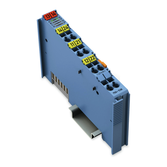
2DO RELAY Ex i 2-Channel Relay Output Module, 100 VAC, 30 VDC, Ex i, isolated outputs, 2 changeover contacts For WAGO-I/O-SYSTEM 750
Brand:
WAGO
| Category:
Control Unit
| Size: 4 MB
Table of Contents
Table of Contents
3
1 Notes about this Documentation
5
Validity of this Documentation
5
Copyright
5
Symbols
6
Number Notation
8
Font Conventions
8
Table 1: Number Notation
8
Table 1: Font Conventions
8
2 Important Notes
9
Legal Bases
9
Subject to Changes
9
Personnel Qualifications
9
Use of the 750 Series in Compliance with Underlying Provisions
9
Technical Condition of Specified Devices
10
Disposal
10
2.1.4.1.1 Electrical and Electronic Equipment
10
2.1.4.1.2 Packaging
11
Safety Advice (Precautions)
12
3 Device Description
15
View
17
Figure 1: View
17
Table 1: Legend for Figure "View
17
Connectors
18
Data Contacts/Local Bus
18
Figure 2: Data Contacts
18
Power Jumper Contacts/Field Supply
19
Figure 3: Power Jumper Contacts
19
Table 1: Legend for Figure "Power Jumper Contacts
19
Cage Clamp
20
Figure 4: CAGE CLAMP ® Connectors
20
Table 1: Legend for Figure "CAGE CLAMP ® Connectors
20
Display Elements
21
Figure 5: Display Elements
21
Table 1: Legend for Figure "Display Elements
21
Operating Elements
22
Schematic Diagram
22
Figure 6: Schematic Diagram
22
Technical Data
23
Device Data
23
Power Supply
23
Communication
23
Table 1: Technical Data - Device
23
Table 2: Technical Data - Power Supply
23
Table 3: Technical Data - Communication
23
Outputs
24
Explosion Protection
24
Connection Type
24
Table 4: Technical Data - Outputs
24
Table 5: Technical Data - Explosion Protection
24
Table 1: Technical Data - Field Wiring
24
Table 13: Technical Data - Power Jumper Contacts
24
Climatic Environmental Conditions
25
Electrical Safety
25
Table 1: Technical Data - Data Contacts
25
Table 1: Technical Data - Climatic Environmental Conditions
25
Table 1: Electrical Safety
26
Approvals
27
Standards and Guidelines
29
4 Process Image
31
Table 1: Output Bits
31
5 Mounting
32
Mounting Sequence
33
Inserting and Removing Devices
34
Inserting the I/O Module
34
Figure 7: Inserting I/O Module (Example)
34
Figure 8: Snap the I/O Module into Place (Example)
34
Removing the I/O Module
35
Figure 9: Removing the I/O Module (Example)
35
6 Connect Devices
36
Connecting a Conductor to the CAGE CLAMP
36
Figure 10: Connecting a Conductor to a CAGE CLAMP
36
Power Supply Concept
37
Figure 11: Supply Principle Ex I
38
Table 1: Legend for Figure "Ex I Power Supply Concept
38
Power Supply Concept for Marine Applications in Ex I
39
Figure 12: Overvoltage Categories
39
Table 1: Legend for Figure "Overvoltage Categories
39
Figure 13: Power Supply Concept for Marine Applications in Ex I - Class a
40
Table 1: Legend for Figure "Power Supply Concept for Marine Applications in Ex I - Class a (Shown with 750-624/XXX-XXX for Field 2)
40
Table 2: Explanation of the Legend for Figure "Power Supply Concept for Marine Applications in Ex I - Class a (Shown with 750-624/XXX-XXX for Field 2)
40
Figure 14: Power Supply Concept for Marine Applications in Ex I - Class B
41
Table 1: Legend for Figure "Power Supply Concept for Marine Applications in Ex I - Class B (Shown with 750-626/XXX-XXX for Field 2)
41
Table 2: Explanation of the Legend for Figure "Power Supply Concept for Marine Applications in Ex I - Class B (Shown with 750-626/XXX-XXX for Field 2)
41
Connection Example
42
Figure 15: Connection Example with 2 Intrinsically Safe Devices
42
Protective Circuits for Contacts of Relay Modules
43
Figure 16: Diode
43
Figure 17: Zener Diode and Diode
43
Figure 18: Suppressor Diode
43
Figure 19: Varistor
43
Table 1: Protective Circuits for Contacts of Relay Modules
43
Figure 20: R/C Combination
44
7 Use in Hazardous Environments
45
Marking Configuration Examples
46
Marking for Europe According to ATEX and Iecex
46
Figure 21: Marking Example According to ATEX and Iecex
46
Figure 22: Text Detail - Marking Example According to ATEX and Iecex
46
Table 1: Description of Marking Example According to ATEX and Iecex
47
Figure 23: Marking Example for Approved Ex I I/O Module According to
48
Figure 24: Text Detail - Marking Example for Approved Ex I I/O Module
48
Table 1: Description of Marking Example for Approved Ex I I/O Module According to ATEX and Iecex
49
Table 1: Description of Marking Example for Approved Ex I I/O Module
49
Marking for the United States of America (NEC) and Canada (CEC)
50
Figure 25: Marking Example According to NEC
50
Figure 26: Text Detail - Marking Example According to NEC 500
50
Table 1: Description of Marking Example According to NEC 500
50
Figure 27: Text Detail - Marking Example for Approved Ex I I/O Module
51
Figure 28: Text Detail - Marking Example for Approved Ex I I/O Module
51
Table 1: Description of Marking Example for Approved Ex I I/O Modules
51
Figure 29: Text Detail - Marking Example for Approved Ex I I/O Modules
52
Table 1: Description of Marking Example for Approved Ex I I/O Modules
52
Installation Regulations
53
Special Notes Including Explosion Protection
53
Special Notes Regarding ANSI/ISA Ex
55
Control Drawing
56
Figure 30: Control Drawing No: 750538
56
List of Figures
57
List of Tables
58
Advertisement
Advertisement
Related Products
WAGO 750-535
WAGO 750-535/040-000
WAGO 750-537/040-000
WAGO 750-539
WAGO 750-536
WAGO 750-532
WAGO WAGO-I/O-SYSTEM 750-508
WAGO 750-564
WAGO 750-557/040-000
WAGO 750-563/040-000
WAGO Categories
I/O Systems
Control Unit
Power Supply
Switch
Controller
More WAGO Manuals
Login
Sign In
OR
Sign in with Facebook
Sign in with Google
Upload manual
Upload from disk
Upload from URL