Advertisement
Quick Links
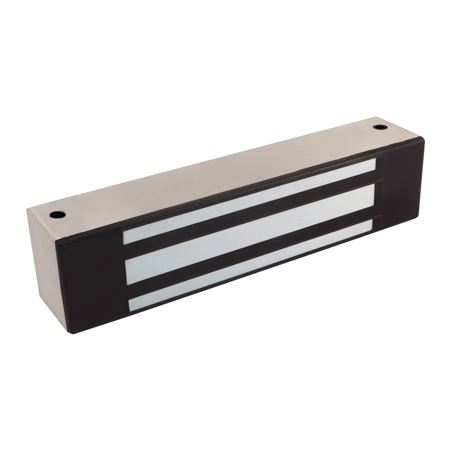
Securitron
Magnalocks
Installation & Operating Instructions
Introduction
The Securitron Magnalock
®
locking, and includes operational electrical characteristics and
mounting configuration options addressed in this document.
The BondSTAT "B" Magnalock Series, Bond Sensor, monitors the magnetic
field. An internal sensor activates a single pole double throw (SPDT)
dry-contact relay connection designed for interface with access control
and/or alarm systems, which reports the status of the Magnalock.
The DPS "D" Magnalock Series, Door Position Sensor, is activated by a
special magnetic strike armature assembly. This isolated SPDT reed switch,
with an internal resettable protection device, is designed to interface
with an access control and/or alarm system to monitor door status.
Product Components
A Magnalock
B Sex Bolt
C Roll Pins (2x)
D Strike Plate
Recommended Tools
• Power Drill
• Hammer
• Wire Strippers/
Cutter
• 1/8", 3/8", 1/2"
Drill Bits
Specifications
Holding Force
600 lbs [272 kg]
Length
Height
Depth
Current at 12 VDC
Current at 24 VDC
Capacitance at 12 VDC
Capacitance at 24 VDC
Dual Voltage
BondSTAT Rating (voltage)
DPS Rating (voltage)
M32 | M62 | M82
®
family is state of the art in electromagnetic
E Funnel Bushing
F Roll Pin
Bushings (2x)
G 5/16-18 Screw
• Center Punch
• Crimp Wire
Connectors
• Masking Tape
• Crimp Tool
• 3/16" Hex Key
(Allen Wrench)
M32
M62
1200 lbs [544 kg]
8" [203 mm]
8" [203 mm]
1.88" [48 mm]
3" [76 mm]
1.6" [41 mm]
1.75" [44 mm]
300 mA
250 mA
150 mA
150 mA
6.8 mF
44 mF
6.8 mF
11 mF
12/24 Volts DC
30 VDC (Maximum) ~ Current 1 Amp (Maximum)
30 VDC (Maximum) ~ Current 125 mA (Maximum)
Diagram 1 Product
Components
H Rubber Washers
I Magnalock
Installation
Template
E
• Fish Tape or
Lead Wire
• Multimeter
• 1/2" Open end or
Crescent Wrench
M82
1800 lbs [816 kg]
12" [305 mm]
3" [76 mm]
1.75" [44 mm]
350 mA
200 mA
44 mF
11 mF
A
B
D
F
G
I
Securitron
M32 Series Magnalock (Standard Mount)
®
Installation Template
Patent pending and/or patent www.assaabloydss.com/patents Copyright © 2020, Hanchett Entry Systems,
Inc., an ASSA ABLOY Group company. All rights reserved. Reproduction in whole or in part without the
express written permission of Hanchett Entry Systems, Inc. is prohibited. 500-10850_7
Instructions
NOTE: See installation instructions for full information and troubleshooting.
1. The relationship between the two magnet
5. Be care not to scrape the magnet cable
mounting holes is critical. DO NOT let
when pushing it back into the frame.
your marking or drilling wander.
6. The two rubber washers stack one on top of the
2. DO NOT over drill the diameter of the 3/8" [9.5 mm]
other and mount in between the strike and the
magnet mounting holes or the blind nuts will
door around the center strike mounting screw.
not seat. It is best to use a center punch to
DO NOT place the washers on the roll pins.
create indentations for all drill locations.
7. When inserting the sex bolt from the outside of
3. Make sure the blind nuts are collapsed.
the door, DO NOT insert it fully until you have
started the mating screw from the other side.
4. DO NOT over tighten the magnet mounting
This insures that the sex bolt will go in straight.
screws. Use provided LOCTITE on screw threads.
CUT ALONG THIS LINE
7.2"
[182.9mm]
.6"
Position edge of magnet 1/2" [12.7mm] from frame corner
Magnet
[15.2 mm]
to provide drilling clearance
2 X Screw Monting Holes:
· Blind nuts used: 3/8" [9.15mm] DIA.
· No blind nuts used: 3/16" [4.18mm] DIA.
.4"
[10.2 mm]
FOLD ALONG THIS LINE
6.25"
[158.8mm]
2 X 1/2" [12.7mm]
3/8" [9.5mm] DIA. Through Door
.813"
1" [25.4mm]
[20.7 mm]
1/2" [12/7mm] DIA. from other
Deep into Door
side for sex bolt
2.25"
[57.2 mm]
.812"
[20.7 mm]
Strike Plate
Vertical Mount: Move strike holes 1/10" [2.5 mm] further from fold line.
Offset Strike: Move strike holes 1/4" [6.4 mm] towards fold line
C
H
WARNING DO NOT DRILL into
magnet or strike for any reason.
8. DO NOT over tighten the strike
mounting screw into the sex bolt.
9. Make sure the strike plate floats and pivots around
the center mounting screw. This compensates
for door misalignment. If the strike is mounted
rigidly, the Magnalock will NOT hold.
10. Use of roll pin plastic bushings is recommended for
metal doors. It the plastic bushings are not used, drill
3/8" [9.5 mm] diameter holes for the strike roll pins.
DO NOT photo copy template.
(Dimensions will change)
.4"
[10.2 mm]
.6"
[15.2 mm]
3/8" [9.5mm] DIA. wire way hole
Header
Door
2.25"
[57.2 mm]
.875"
[22.2 mm]
CUT ALONG THIS LINE
1 of 8
Advertisement

Subscribe to Our Youtube Channel
Related Manuals for Assa Abloy Securitron Magnalock M32


Summary of Contents for Assa Abloy Securitron Magnalock M32
- Page 1 • 1/8", 3/8", 1/2" • Crimp Tool Inc., an ASSA ABLOY Group company. All rights reserved. Reproduction in whole or in part without the express written permission of Hanchett Entry Systems, Inc. is prohibited. 500-10850_7 WARNING DO NOT DRILL into magnet or strike for any reason.
-
Page 2: Pre-Installation Survey
Perform a Diagram 2 Typical Magnalock Installation on an Out-Swinging Door Pre-Installation Survey NOTE: Additional brackets may be needed for proper Bracket installation. Specialized brackets are available through DOOR Blind Nuts Securitron and its many product distributors. FRAME PERFORM an initial on-site survey to determine a method of mounting and to review the installation plan, taking the following into consideration: SFB Bracket... - Page 3 Attach the Template and Diagram 4 Attaching the Template Mark the Drill Holes SELECT a mounting location for the Magnalock and strike assembly. NOTE: The edge of the template should be about 1" [25.4 mm] from the latch side of the door to allow proper access at the mounting locations for drilling and tool access.
- Page 4 Install the Strike Plate Diagram 9 Seating the Roll Pins Using a hammer, TAP the roll pins into the strike plate until seated. Protect face of strike to prevent damage. (see Diagram 9). INSERT the 5/16-18 bolt through the funnel bushing and strike plate (see Diagram 10).
- Page 5 Install the Magnalock Diagram 13 Secure Maglock body and add finishing caps PULL the lock wire into frame and to desired location. APPLY thread lock to mounting screws. MOUNT lock body to frame using supplied hardware (see Diagram 13). INSERT the tamper finish caps into the mounting screw holes (see Diagram 13).
- Page 6 Wiring Diagram 15 Typical Magnalock Connections WARNING: A shock hazard may occur if the Standard Version Access Power Supply Magnalock is operated from a DC power supply that 2-wire Magnalock Control Device is connected to earth ground or not isolated. CAUTION: The Magnalock must be operated from VAC Input BLACK...
- Page 7 BondStat Diagram 19 Connections Double Door Status GREEN WHITE BondSTAT BondSTAT WHITE GREEN Magnalock Magnalock When two Magnalocks are used for double door installation, the BondSTAT contacts should be wired in series for proper reporting. CONNECT the GREEN wire of one lock to the WHITE wire of the other (see Diagram 19).
-
Page 8: Warranty
For information on warranty coverage and replacement options, please visit assaabloyesh.com/warranty Patent pending and/or patent www.assaabloydss.com/patents Copyright © 2020, Hanchett Entry Systems, Inc., an ASSA ABLOY Group company. techsupport.esh@assaabloy.com | assaabloyesh.com All rights reserved. Reproduction in whole or in part without the express written 800 626 7590 | 10027 S.
Need help?
Do you have a question about the Securitron Magnalock M32 and is the answer not in the manual?
Questions and answers