Rice Lake iDimension Plus Assembly Instructions Manual
Static dimensioning system
Hide thumbs
Also See for iDimension Plus:
- Manager's manual (68 pages) ,
- Setup and operation manual (60 pages) ,
- Assembly instructions manual (26 pages)

Related Manuals for Rice Lake iDimension Plus


Summary of Contents for Rice Lake iDimension Plus
- Page 1 iDimension Plus ® Static Dimensioning System Assembly Instructions November 4, 2019 PN 197164...
- Page 2 All information contained within this publication is, to the best of our knowledge, complete and accurate at the time of publication. Rice Lake Weighing Systems reserves the right to make changes to the technology, features, specifications and design of the equipment without notice.
-
Page 3: Table Of Contents
Attach Scanning Head ............... . . 7 Technical training seminars are available through Rice Lake Weighing Systems. - Page 4 Plus Rice Lake continually offers web-based video training on a growing selection of product-related topics at no cost. Visit www.ricelake.com/webinars www.RiceLake.com Visit our website...
-
Page 5: Introduction
The iDimension Plus QubeVu Manager Guide (PN 195441) provides a detailed overview of the QubeVu Manager, the embedded firmware of the iDimension Plus. The QubeVu Manager is a set of tools provided to set up and configure the iDimension Plus in any environment. These tools are recommended for use by a technical systems administrator. -
Page 6: Safety
Operate between 41–104º F (5–40º C). Never remove the iDimension Plus head cover or the electrical connection panels at the base of the pole assembly. Never modify or attempt to repair the unit. Service must be performed by Rice Lake Weighing Systems only. -
Page 7: Overview
Keep calibration object for future use. Note Immediately after unpacking the iDimension Plus, visually inspect the contents to ensure all components are included and undamaged. If any parts were damaged in shipment, notify Rice Lake Weighing Systems and the shipper immediately. -
Page 8: Assembly
Plus Assembly This section provides an overview of iDimension Plus assembly instructions. Unit Assembly To assemble the iDimension Plus, follow the procedure below. 3.1.1 Pole Assembly 1. Locate the two hex screws and two Phillips screws pre-installed at the pole joint of the upper pole assembly. -
Page 9: Attach Base
5. Install the base plate by inserting the guide pins into the alignment slot and alignment hole from Figure 3-4, using the four screws removed in Step 2 with the 3 mm hex wrench. Hex Screws Hex Screws Figure 3-6. Base Plate Bottom view © Rice Lake Weighing Systems ● All Rights Reserved... -
Page 10: Attach Display
Plus 3.1.3 Attach Display 1. Using a 3 mm hex key, remove the pre-installed hex screw from the pole assembly display bracket. Hex Screw Figure 3-7. Pole Assembly Display Bracket 2. Secure the display mount to the pole assembly display bracket using the previously removed screw. -
Page 11: Attach Scanning Head
Step 9 on page 10 for instructions on how to reinstall the Phillips screws. Scanning Head Spacer Block with Mounting Screws Phillip Screws (3) Cable Slot Rear Cover Figure 3-12. Scanning Head Parts © Rice Lake Weighing Systems ● All Rights Reserved... - Page 12 Plus 3. Loosen the three mounting screws so the screws are .25'' from the spacer plate. Mounting Screws Keyholes Figure 3-13. Mounting Screws and Key Holes 4. Insert the cables from the upper pole assembly through the cable slot on the rear enclosure.
- Page 13 Ethernet Port Open USB Port SD Card (Not Supported) HDMI Port (Not Supported) Display Connection USB Port at Electrical Base Table 3-1. Scanning Head Connection List Figure 3-18. Scanning Head Connections © Rice Lake Weighing Systems ● All Rights Reserved...
- Page 14 Plus 9. Reinstall the scanning head rear cover using the three small Phillips screws removed within Step 7 on page Phillips Screw Phillips Screw Figure 3-19. Scanning Head with Rear Cover Secured Phillips Screw Figure 3-20. Scanning Head with Rear Cover Secured Continued www.RiceLake.com...
- Page 15 Ethernet Port (used to connect to network in order to interface compatible software) Power (DC in) - 24 V1 Table 3-2. Electrical Base connections Prior to powering on the iDimension Plus, see the iDimension Plus Operation Manual (PN 195439) for system setup Note and configuration 11.
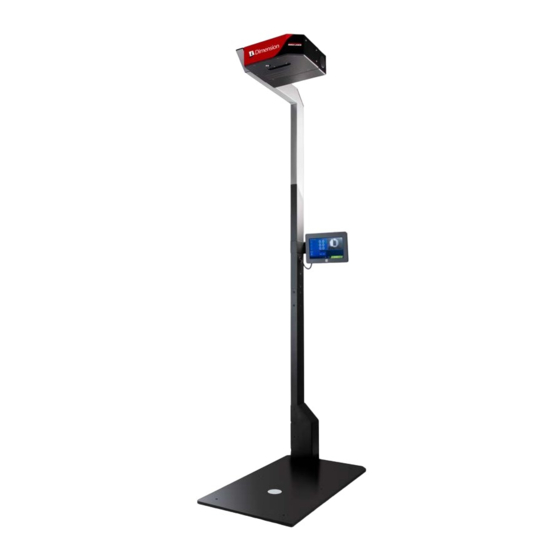
- Page 16 Plus 12. The fully assembled iDimension Plus should resemble Figure 3-23. Figure 3-23. Assembled iDimension Plus www.RiceLake.com Visit our website...
- Page 18 Specifications subject to change without notice. Rice Lake Weighing Systems is an ISO 9001 registered company. 230 W. Coleman St. • Rice Lake, WI 54868 • USA U.S. 800-472-6703 • Canada/Mexico 800-321-6703 • International 715-234-9171 • Europe +31 (0)26 472 1319 November 4, 2019 www.ricelake.com...
Need help?
Do you have a question about the iDimension Plus and is the answer not in the manual?
Questions and answers