Table of Contents
Advertisement
Quick Links
Advertisement
Table of Contents

Related Manuals for Rice Lake ISHIDA IP-AI


Summary of Contents for Rice Lake ISHIDA IP-AI
- Page 1 IP-AI Prepack Scale & Printer Service Manual PN 179840...
- Page 2 All information contained within this publication is, to the best of our knowledge, complete and accurate at the time of publication. Rice Lake Weighing Systems reserves the right to make changes to the technology, features, specifications and design of the equipment without notice.
-
Page 3: Introduction
Introduction Introduction ● Purpose of this Manual The purpose of this manual is as reference material for the delivery, installation, repair and maintenance of the IP-AI. ● Target Readers This manual has been written specifically for use by our service personnel. The use of this manual by any person other than the above is strictly prohibited. -
Page 4: Table Of Contents
Introduction Table of Contents Revision History ....................... 1 Introduction ....................... 2 Chapter 1 Overview ................... 1-1 1.1 Specifications ....................1-1 1.2 Features ......................1-4 1.3 Name of Each Part ..................1-5 1.4 Dimensions ...................... 1-6 1.5 Items Required for Installation ............... 1-7 1.6 Installation Space .................... - Page 5 Introduction 2.7 Curling inward label correspondence (Optional) ........2-26 Chapter 3 Electric Components ................3-1 3.1 PCB Configuration of the Electric Part ............3-1 3.1.1 Main Board ..................... 3-1 3.1.2 Key Control Board ..................3-4 3.1.3 Scale Board ....................3-5 Chapter 4 Setup Mode..................
- Page 6 Introduction 4.12 CUSTOM BARCODE .................. 4-43 4.12.1 CUSTOM BARCODE (BASIC) ............... 4-44 4.12.2 CUSTOM BARCODE (PREVIEW) ............4-46 4.13 MENU TITLE ....................4-47 4.13.1 MENU TITLE (OPERATE) ..............4-47 4.14 OPERATION SETTING ................4-48 4.14.1 OPERATION SETTING (CALL1) ............4-48 4.14.2 OPERATION SETTING (CALL2) ............
- Page 7 Introduction 5.12.2 DOWNLOAD (SUB APP.) ............... 5-23 5.12.3 DOWNLOAD (SUB BOOT) ..............5-24 5.13 OPTION CHECK ..................5-25 5.13.1 OPTION CHECK (SCANNER) ............... 5-25 5.13.2 OPTION CHECK(USB) ................5-26 5.13.3 OPTION CHECK (DEVICE) ..............5-27 5.14 DISPLAY CAPTURE ................... 5-28 5.15 GRAVITY.....................
-
Page 8: Chapter 1 Overview
Chapter 1 Overview Chapter 1 Overview Specifications Items Descriptions Product name IP-AI Product classification Weight price labeler Use conditions Temperature 0°C to 40°C, Humidity 20% to 85% (Non condensing) *The printable environment depends on the label specifications. Installation status Installation on an IP stand or a work table Option Name file stand Numerical keypad cover... - Page 9 Chapter 1 Overview Items Descriptions Label roll diameter Paper pipe inner diameter φ76mm Maximum outer diameter φ224mm Label storage 5000 labels (42mm, 2.5mm gap) capacity Label size Label width 20mm to 80mm Label length 20mm to 150mm *Label backing paper width 82mm max. Issuing method Switchable between label peeling-off and continuous label printing.
- Page 10 Chapter 1 Overview Items Descriptions Safety Ishida product safety standards Signal word standards CE marking · UL · cUL Standards Compliant with Ishida product standards and Ishida sanitation standards Japanese Measurement Act NTEP (USA) · OIML(Europe)
-
Page 11: Features
Chapter 1 Overview Features The display has been changed to 12.1 inches and the thermal head to 12 dots/mm based on IP-UNI. The larger display allows elderly operators to easily see and contributes to prevention of operation mistakes. High-accuracy printing contributes to creating stores that are safe and secure for consumers. -
Page 12: Name Of Each Part
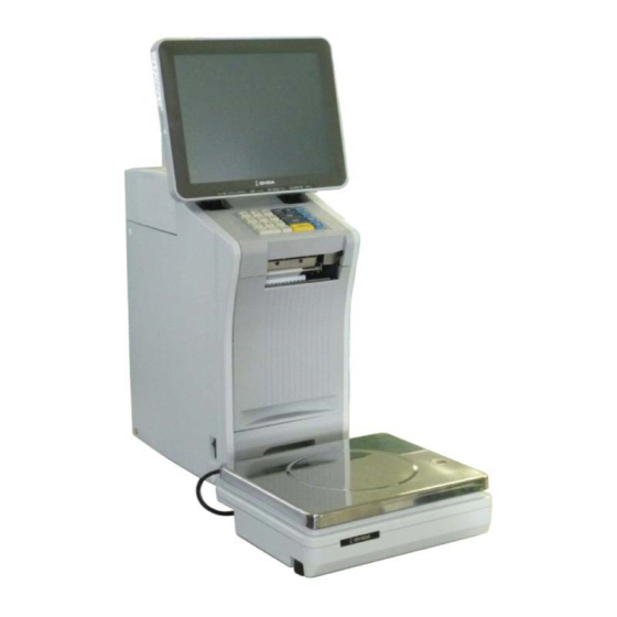
Chapter 1 Overview Name of Each Part Front view Touch panel Keypad Power switch Label outlet Label cassette (“Label printer” in the operation manual) Scale unit Level Level adjustable leg NOTE: The label cassette is called the label printer in the operation manual. The label cassette of the machine is not replaceable. -
Page 13: Dimensions
Chapter 1 Overview Dimensions The following drawing shows the dimensions. Make sure to secure a carry-in route and space required for setup and maintenance. Unit: mm... -
Page 14: Items Required For Installation
Chapter 1 Overview Items Required for Installation Description Check □ Balance weight (6kg, equivalent to M1 class) USB memory □ (that stores data of the user) □ Labels □ Phillips head screwdriver... -
Page 15: Installation Space
Chapter 1 Overview Installation Space Secure sufficient working space on the left and right side of the machine. Space for label replacement 300 mm... -
Page 16: Power Supply
Chapter 1 Overview Power Supply 100VAC outlet This machine requires single-phase 100VAC power supply with 4A capacity. The shape and rating of the power plug are illustrated. Power plug Prepare an outlet which conforms to the standards. Noise or a voltage drop in the power supply ... -
Page 17: Carry-In And Installation
Chapter 1 Overview Carry-in and Installation 1.8.1 Installation Procedure Check Sheet Step Description Check Carry in IP-AI. (Total weight 25kg) □ ・ Confirm the installation place. □ Connect the cable of the weighing unit to the main unit. * Make an adjustment so that the bubble is located at the center of the level □... -
Page 18: Setup
Chapter 1 Overview Setup 1.9.1 Requirements for Setup USB flash memory (that stores data of the user) Balance weight (6kg, equivalent to M1 class) 1.9.2 Setup Procedure Perform a setup operation in the [Setup Mode] and the [Adjust Mode] on the maintenance screen whose authority is controlled with login. - Page 19 Chapter 1 Overview (USB memory stick) Recommended product Product No.:0001495390** Product Name: Hagiwara, USB, 1G NOTE: Please note that the recommended USB memory is subject to change without notice. 3) Items required for checking (Setup Mode) Password Item data auto update ...
-
Page 20: Operation Checks
Chapter 1 Overview 1.9.3 Operation Checks ■ Weighing check Place a balance weight (6 kg, equivalent to M1 class) on the weighing platter and confirm that the displayed weight is within 6,000 g 1 scale unit (2 g). ■ Four-corner check Place a weight (approximately 3kg but not heavier) on the center and four corners of the weighing platter, and conform that the difference between the center and four corners is within 1 scale unit (1 kg). -
Page 21: Chapter 2 Mechanical Adjustment
Chapter 2 Mechanical Adjustment Chapter 2 Mechanical Adjustment Removing Case Covers NOTE Remove the case covers in the following order: case body (top), case bodies (right & left), and case bodies (rear & scale cable). 2.1.1 Case Body (Top) Cover guard (1) Remove the cover guard by sliding it in the (2) Remove the two screws A, and remove the direction of the arrow. -
Page 22: Case Body (Right Side)
Chapter 2 Mechanical Adjustment 2.1.3 Case Body (Right Side) Case body (right side) Case body (right side) Label cassette (5) After pulling out the label cassette, loosen the (6) Remove two caps, two screws F and the two screws E. stepped screw G, and then remove the case body (right side). -
Page 23: Replacing Prats
Chapter 2 Mechanical Adjustment Replacing Prats 2.2.1 Replacing the Thermal Head (1) Pull out the label cassette. Thermal head (2) Remove the two hexagonal head screws A. (3) Pull out the thermal head forward. Connector Bracket head (4) Pull out the connector for the thermal head. (5) Remove the two screws and remove the bracket head. -
Page 24: Adjusting The Thermal Head Position
Chapter 2 Mechanical Adjustment 2.2.2 Adjusting the Thermal Head Position A Fixing screw B Printer bracket C Thermal head stay End face bracket D Bracket head End face stay ○ Adjustment by stay movement Head contact (unevenness) (Shift to back and front) Print shift to right and left If the print density is uneven or the print is light when test labels are issued, the thermal head may not be positioned properly. - Page 25 Chapter 2 Mechanical Adjustment c. When the print density differs between the right and left sides The thermal head on the side that has the lighter print is shifted to the back or front from the center line of the print roller. By referring to the figure, loosen the fixing screws A, and shift and adjust the fixing screws so that the left and right sides of the thermal head are parallel to the center line of the print roller when viewed from above (this means the center lines are aligned.)
-
Page 26: Replacing The Print Roller
Chapter 2 Mechanical Adjustment 2.2.3 Replacing the Print Roller (1) Pull out the label cassette. Gear E-rings Left bracket (2) Remove the stepped screw A and the screw B (3) Remove the E-rings (from two points) and and remove the left bracket. remove the gear. - Page 27 Chapter 2 Mechanical Adjustment E-rings Print roller Mark Print roller (front) Protruding part E-ring Gear (8) After replacing the print roller, mount it in the The diameters of the front and NOTE reverse order of the removal procedure. rear sides of the print roller are different.
-
Page 28: Replacing The Peeling Sensor
Chapter 2 Mechanical Adjustment 2.2.4 Replacing the Peeling Sensor (1) Pull out the label cassette approximately 2 cm to 3 cm. Keyboard unit Connector Keyboard unit (2) Remove the two screws A and open the (3) Remove the two connectors and remove the keyboard unit. -
Page 29: Replacing The Label Sensor
Chapter 2 Mechanical Adjustment 2.2.5 Replacing the Label Sensor (1) Pull out the label cassette. Label sensor harnesses Cable tie Bracket Connector Label sensor harnesses (2) Remove the claws B (from three points ) and (3) Remove the connector for the label sensor remove the bracket that holds the label sensor harnesses and cut the cable tie. -
Page 30: Replacing The Head Up Sensor
Chapter 2 Mechanical Adjustment 2.2.6 Replacing the Head Up Sensor (1) Remove the case body (top) and case body (left side). (Refer to page 2-1.) Clamps Head up sensor connector Head up sensor harness (2) Remove the head up sensor connector for the (3) Remove the two screws A and three clamps main board. -
Page 31: Replacing The Keyboard
Chapter 2 Mechanical Adjustment 2.2.7 Replacing the Keyboard (1) Remove the keyboard unit by following the procedure to replace the peeling sensor. (Refer to page 2-8). Bracket Keyboard Peeling sensor (2) Remove the screw B and remove the peeling (3) Remove the four screws C, remove the sensor. -
Page 32: Replacing The Main Board
Chapter 2 Mechanical Adjustment 2.2.8 Replacing the Main Board (1) Remove the case body (top). (Refer to page 2-1.) Connector case Main board (2) Remove the two hexagonal head screws A, (3) Remove the connectors a to i from the nine one screw B, two screws C, and then remove points. -
Page 33: Replacing The Power Supply Board
Chapter 2 Mechanical Adjustment 2.2.9 Replacing the Power Supply Board Overturning prevention bracket AC power code cover Main body (1) Overturn the main unit as shown in the figure. (2) Remove the screw B and then remove the AC power code cover. AC power code (3) Pull out the AC power cord and remove. -
Page 34: Replacing The Motor
Chapter 2 Mechanical Adjustment 2.2.10 Replacing the Motor (1) Remove the case body (top) and case body (left). (2) Overturn the main unit by referring to the procedure to replace the power supply board, and open the bottom plate. (Refer to page 2-13.) Motor Motor Claw... -
Page 35: Adjusting The Belt Tension
Chapter 2 Mechanical Adjustment 2.2.11 Adjusting the Belt Tension (1) Remove the case body (left side). (Refer to page 2-1.) (2) Make an adjustment so that the belt is deflected by 3.2 mm when a position near the center of the belt is pressed with a finger with a force of 200g (1.96N). -
Page 36: Replacing The Scale Cable
Chapter 2 Mechanical Adjustment 2.2.12 Replacing the Scale Cable (1) Remove all the case bodies except for the case body (rear). (Refer to pages 2-1 and 2-2.) Scale cable Connector Cable clamp Scale cable (2) Remove the scale cable from the two cable (3) Remove the connector for the scale cable. -
Page 37: Adjusting The Ball Catch Position
Chapter 2 Mechanical Adjustment 2.2.13 Adjusting the Ball Catch Position Adjust the catch position for the cassette lock. If the label cassette is pushed forward, the position needs to be adjusted. (1) Remove the case body (top), case body (right side) and case body (rear). -
Page 38: Replacing The Display Unit
Chapter 2 Mechanical Adjustment Replacing the Display Unit 2.3.1 Replacing the Display Board (1) Remove the case body (top). (Refer to page 2-1) Hinge cover (2) Remove the connectors a and b. (3) Remove the two screws A and remove the hinge cover. -
Page 39: Replacing The Display
Chapter 2 Mechanical Adjustment 2.3.2 Replacing the Display (1) Remove the rear cover by following steps 1 to 5 of the procedure to replace the display board. (Refer to page 2-21.) Display harness 1 (2) Remove the connector a. (3) Remove the screw A and remove the display harnesses 1 and 2 from the harness clamp. -
Page 40: Replacing The Touch Panel
Chapter 2 Mechanical Adjustment Bracket (7) Remove the four screws E and remove the (8) Lay the display face down, remove the four display from the bracket. hexagonal screws F, and remove the connectors b and c. (9) After replacing the display, mount it in the reverse order of the removal procedure. -
Page 41: Replacing The Weighing Unit
Chapter 2 Mechanical Adjustment Replacing the Weighing Unit After replacing the load cell and A/D board and adjusting the span, it is necessary to do NOTE a verification test after attaching a new approval seal. Weighing platter Weighing platter support (1) Remove the weighing platter. - Page 42 Chapter 2 Mechanical Adjustment A/D board Load cell unit Harness holder (5) Remove the solder d from the five points, (6) Remove the two socket head bolts E with a remove the board holders D from the four hexagon wrench. points, and then remove the A/D board.
-
Page 43: Replacing The Numerical Keypad Cover (Optional)
Chapter 2 Mechanical Adjustment Replacing the Numerical Keypad Cover (Optional) (1) Lift up the part A, remove the numerical Numerical keypad cover keypad cover pressing in the direction of the arrow 1 while removing the claws B from four points. (2) Remove the numerical keypad cover (optional) in the direction of the arrow 2, and replace it. -
Page 44: Wireless Lan Kit Overseas Edition Expansion (Optional)
Chapter 2 Mechanical Adjustment 2.6 Wireless LAN kit overseas edition expansion (Optional) Plate B 'blank' (1) Open the side cover. (2) Remove the cover 'blank'. Positions to fasten the screws that are Remove the screws on these two positions. included at shipping. (3) Remove the upper cover. - Page 45 Chapter 2 Mechanical Adjustment (6) Antenna mounting (7) Put the bracket 'FAN' back to the based position . (8) In the case of the United States and Canada specifications, put the following sticker in the space vacated on the nameplate. 2-25...
-
Page 46: Curling Inward Label Correspondence (Optional)
Chapter 2 Mechanical Adjustment Curling inward label correspondence (Optional) Remove this damper unit. Remove the screw. Remove this damper unit. Remove these two positions of the screws and pull the damper unit. Then, put the screws back to the original position. (1) Open the side cover. -
Page 47: Chapter 3 Electric Components
Chapter 3 Electric Components Chapter 3 Electric Components PCB Configuration of the Electric Part Before putting your fingers or hand into the main unit, be sure to press the DANGER emergency stop switch. Please note that 24 VDC power supply for the logic system will not be turned off CAUTION even if the emergency stop switch is pressed. - Page 48 Chapter 3 Electric Components Connectors Connector No. Connected to Reference Not used. Not used. Not used. Not used. Not used. Not used. Not used. Not used. XJ10 Stepping motor XJ11 Not used. XJ12 Not used. XJ13 Power supply XJ14 Not used.
- Page 49 Chapter 3 Electric Components DIPSW Switch name Switch No. Setting Remarks Always OFF Always OFF Always OFF Always OFF Battery Type ON/OFF Replacement Turned ON with socket inserted Short pin into 1-2.
-
Page 50: Key Control Board
Chapter 3 Electric Components 3.1.2 Key Control Board P1102-4 (Product No. 100-003-3188-**) XJ1: To LCD XJ9: To XJ19 of main board XJ4: To Numerical key relay XJ6: To touch panel Connectors Connector No. Connected to Reference Not used. Not used. Not used. -
Page 51: Scale Board
Chapter 3 Electric Components 3.1.3 Scale Board P-1111A-2 (Product No. 100-003-3404-**) SW1(SW2) memory SW To load cell(solder-mounted) To main board (P-1100A-2) Connectors Connector No. Connected to Reference P-1100 main board Not used. Not used. Not used. Load cell DIP switch Switch name Switch No. - Page 52 Chapter 3 Electric Components...
-
Page 53: Chapter 4 Setup Mode
Chapter 4 Setup Mode Chapter 4 Setup Mode Startup Turn on the power. Power switch The PREPACK screen in the OPERATE mode appears. Press at the upper right side of the screen. The menu appears in the OPERATE MODE. Press the [SET UP] button on the screen. - Page 54 Chapter 4 Setup Mode The User Menu screen in the Setup mode appears. Input the password “495344” using the numerical keys, and press the [LOGIN] button on the screen. The Maintenance Menu screen appears in the Setup mode. Maintenance Menu screen 1/2 Maintenance Menu screen 2/2...
-
Page 55: Machine No. Setting
Chapter 4 Setup Mode MACHINE NO. SETTING 4.2.1 MACHINE No. (BASIC) Menu name Specification Return to Menu. Other tabs also have the same function. Set the machine No. NETWORK No. Input range: 0 to 9999 Select one of the stand-alone, master or satellite machines. ALONE / MASTER / SAT. -
Page 56: Machine No. (Ip Addr.)
Chapter 4 Setup Mode 4.2.2 MACHINE No. (IP ADDR.) Menu name Specification Set the IP address. IP ADDRESS Input range: “0.0.0.0” to “255.255.255.255” Set the subnet mask. SUBNET MASK Input range: “0.0.0.0” to “255.255.255.255” Set the default gateway. DEFAULT GATEWAY Input range: “0.0.0.0”... -
Page 57: Machine No. (Pc Com)
Chapter 4 Setup Mode 4.2.3 MACHINE No. (PC COM) Menu name Specification Set the PC's IP address. PC IP ADDRESS Input range: “0.0.0.0” to “255.255.255.255” Set the PC's port No. PC PORT No. Input range: 0 to 65535 Set the command check period. COM CHECK PERIOD (SEC) Input range: 0 to 9999... -
Page 58: Machine No. (Wifi)
Chapter 4 Setup Mode 4.2.4 MACHINE No. (WiFi) Menu name Specification Select the method of security/authentication/encryption. SECURITY / NONE / WEP64 / WEP128 / WEP64 Shared Key / WEP128 ShKey / AUTHENTICATION WPA PSK TKIP / WPA PSK CCMP / WPA2 PSK TKIP / WPA2 PSK / ENCRYPTION CCMP Set the SSID. -
Page 59: Machine No. (Global Sv.)
Chapter 4 Setup Mode 4.2.5 MACHINE No. (GLOBAL SV.) Menu name Specification GLOBAL SERVICE Select and set whether or not to use the cloud function (Global ENABLE Service). The following parameters are valid only when the GLOBAL SERVICE ENABLE setting is set to [ENABLE] (grayed out when set to [DISABLE]) Set the URL of Cloud server (only when the function is valid). -
Page 60: Machine No. (Sync.)
Chapter 4 Setup Mode 4.2.6 MACHINE No. (SYNC.) Menu name Specification CLOCK SYNC. Select and set whether or not to use the clock synchronization. WITH NTP SERVER Set the URL of NTP server. NTP SERVER URL When this function is not in use, the option is grayed out. Press the button to open the Editor screen to edit. -
Page 61: Machine No. (Outside Printer)
Chapter 4 Setup Mode 4.2.7 MACHINE No. (OUTSIDE PRINTER) Menu name Specification Select and set the connection method for external printer. CONNECT USB / LAN Set the IP address of the printer when the LAN connection is selected IP ADDRESS When the USB is selected, this option is grayed out. -
Page 62: Password
Chapter 4 Setup Mode PASSWORD 4.3.1 PASSWORD (OPERATE) Menu name Specification Set the password in six digits. PASSWORD Logging in by this password will release the menu operation prohibited status. Display the menu name. MENU NAME Both USE and NO USE for SALES are grayed out because SALES cannot be locked with the password. -
Page 63: Key Lock
Chapter 4 Setup Mode KEY LOCK 4.4.1 KEY LOCK (DISPLAY KEY) Menu name Specification Set the password in six digits. PASSWORD Normally in the PRODUCTION screen, enter this password and press KEY LOCK FUNCTION to release the input prohibited status. KEY NAME Display the measurement menu on the normal mode screen. -
Page 64: Key Lock (Function Key)
Chapter 4 Setup Mode 4.4.2 KEY LOCK (FUNCTION KEY) Menu name Specification Set the password in six digits. PASSWORD Normally in the PRODUCTION screen, enter this password and press KEY LOCK FUNCTION to release the input prohibited status. KEY NAME Display the function key name. -
Page 65: Key Lock (Stroke Key)
Chapter 4 Setup Mode 4.4.3 KEY LOCK (STROKE KEY) Menu name Specification Set the password in six digits. PASSWORD Normally in the PRODUCTION screen, enter this password and press KEY LOCK FUNCTION to release the input prohibited status. KEY NAME Display the stroke key name. -
Page 66: Data Storage
Chapter 4 Setup Mode DATA STORAGE 4.5.1 DATA STORAGE (TOTAL ADD.) Menu name Specification MENU NAME Display the menu name. Select whether or not to add. SELECT NON ADD / ADD The TOTAL PROC. / TRANSACTION / STORAGE tabs are displayed only when you access above menus after logging in with the service password. -
Page 67: Data Storage (Total Proc.)
Chapter 4 Setup Mode 4.5.2 DATA STORAGE (TOTAL PROC.) Menu name Specification Select the addition weight of fixed-price items. FIX PRICE ITEM ADD WEIGHT FIX WEIGHT / REAL WEIGHT WRAP MODE Select and set whether or not to perform Weight Add in the production WEIGHT ADD in the WRAP mode. -
Page 68: Data Storage (Transaction)
Chapter 4 Setup Mode 4.5.3 DATA STORAGE (TRANSACTION) Menu name Specification Select whether or not to add the product transaction. PROD. TRANSACTION NON ADD / ADD Select between stopping or overwriting the transaction addition at full TRANS. MEM. memory condition. FULL STOP / OVERWRITE 4-16... -
Page 69: Data Storage (Storage)
Chapter 4 Setup Mode 4.5.4 DATA STORAGE (STORAGE) Menu name Specification Select where to save the transaction. TRANSACTION BUILT-IN / CARD / USB 4-17... -
Page 70: Plu Overwrite
Chapter 4 Setup Mode PLU OVERWRITE Menu name Specification PLU MASTER LIST Display the PLU master item. Select whether or not to automatically update the PLU master item. SELECT YES / NO 4-18... -
Page 71: Plu Initial Data
Chapter 4 Setup Mode PLU INITIAL DATA 4.7.1 PLU INITIAL DATA (SALE1) Menu name Specification Used to enter fractions. (Valid only when entering the fixed No. of items.) Other tabs also have the same function. (Each item) Set the initial value to newly create the PLU master. 4-19... -
Page 72: Plu Initial Data (Msg.)
Chapter 4 Setup Mode 4.7.2 PLU INITIAL DATA (MSG.) Menu name Specification (Each item) Set the initial value to newly create the PLU master. 4-20... -
Page 73: Plu Initial Data (Image)
Chapter 4 Setup Mode 4.7.3 PLU INITIAL DATA (IMAGE) Menu name Specification Set the initial value to newly create the PLU master. (Each item) Pressing an image number item displays the image list. 4-21... -
Page 74: Plu Initial Data (Print)
Chapter 4 Setup Mode 4.7.4 PLU INITIAL DATA (PRINT) Menu name Specification (Each item) Set the initial value to newly create the PLU master. 4-22... -
Page 75: Plu Initial Data (Date)
Chapter 4 Setup Mode 4.7.5 PLU INITIAL DATA (DATE) Menu name Specification (Each item) Set the initial value to newly create the PLU master. 4-23... -
Page 76: Plu Initial Data (Code)
Chapter 4 Setup Mode 4.7.6 PLU INITIAL DATA (CODE) Menu name Specification (Each item) Set the initial value to newly create the PLU master. 4-24... -
Page 77: Plu Initial Data (Wrap)
Chapter 4 Setup Mode 4.7.7 PLU INITIAL DATA (WRAP) Menu name Specification (Each item) Set the initial value to newly create the PLU master. 4-25... -
Page 78: Plu Update
Chapter 4 Setup Mode PLU UPDATE Menu name Specification Set the start No. of the batch change range. START No. Input range: 1 to 99999999 Set the end No. of the batch change range. END No. Input range: 1 to 99999999 Set the unit price No. -
Page 79: Label Comb
Chapter 4 Setup Mode LABEL COMB Menu name Specification CHANGE FORMAT Open the LABEL COMB.(BASIC) screen. COMMON LABEL Set the print pattern to [COMMON LABEL ONLY]. ONLY 4-27... -
Page 80: Label Comb.(Basic)
Chapter 4 Setup Mode 4.9.1 LABEL COMB.(BASIC) Menu name Specification LABEL GROUP Select the label group to display in the list. LABEL TYPE Select the label type. Display the printer to print the label type displayed in the left. PRINTER Pressing this button sets to the feed format of the printer. -
Page 81: Label Comb.(Label)
Chapter 4 Setup Mode 4.9.2 LABEL COMB.(LABEL) Menu name Specification Select or set the printer by entering the number. PRINTER Only the printer connected can be set. Set the label master No. Input range: 1 to 99 LABEL No. If there is no set master, the [LABEL SETTING MASTER IS NOT PROGRAMMED] dialog appears to ask whether to create a new master. - Page 82 Chapter 4 Setup Mode Menu name Specification Select whether or not to set the back feed. BACK FEED NO/YES Set the label sensor distance. SENSOR DISTANCE Input range: 0 to 99.9 Set the feed length. FEED LENGTH Input range: 0 to 99.9 When printing the second line, feeding of the printed label is stopped and resumed again immediately when the pasting machine absorbs the label.
-
Page 83: Label Comb.(Upper Fix)
Chapter 4 Setup Mode 4.9.3 LABEL COMB.(UPPER FIX) Menu name Specification When the paste type is set to FIXED, display the printer to print the label. PRINTER Move to the PRINTER SELECT screen. When the paste type is set to FIXED, set the format to be used in the label printing. -
Page 84: Label Comb. / Detail
Chapter 4 Setup Mode 4.9.4 LABEL COMB. / DETAIL Menu name Specification Display the printer for label printing. PRINTER Move to the PRINTER SELECT screen. Set the format to be used in the label printing. FORMAT Input range: 1 to 999 CASSET. -
Page 85: Label Format
Chapter 4 Setup Mode 4.10 LABEL FORMAT Menu name Specification PRINT CONTROL Open the PRINT CONTROL screen. DETAIL Move to the LABEL FORMAT/DETAIL (BASIC) screen. DELETE Return the selected format to the default status. Display the format No. DESCRIPTION Display the format title. Set the format width. -
Page 86: Label Format / Print Control
Chapter 4 Setup Mode 4.10.1 LABEL FORMAT / PRINT CONTROL Menu name Specification Select the M price print. M PRICE PRINT BAR ONLY / BAR & D.LINE / D.LINE & M.PRI 4-34... -
Page 87: Label Format / Detail (Basic)
Chapter 4 Setup Mode 4.10.2 LABEL FORMAT / DETAIL (BASIC) Menu name Specification Touch the button to open the format name edit screen. FORMAT NAME Touch "<" and ">" located at both sides of the box to select the next (or previous) format master. - Page 88 Chapter 4 Setup Mode Menu name Specification FEED Feed the label. Perform test printing by the format called and the item information set PRINT by PLU No. UNIT ERASE Delete the selected unit. Enter the numerical number and press COPY to copy the said COPY numerical number's format.
-
Page 89: Label Format / Detail (Unit)
Chapter 4 Setup Mode 4.10.3 LABEL FORMAT / DETAIL (UNIT) Menu name Specification Touch the button to open the format name edit screen. FORMAT NAME Touch "<" and ">" located at both sides of the box to select the next (or previous) format master. - Page 90 Chapter 4 Setup Mode Menu name Specification Add the unit. UNIT ADD The header unit also increases by one at the same time. 4-38...
-
Page 91: Label Format / Detail (Preview)
Chapter 4 Setup Mode 4.10.4 LABEL FORMAT / DETAIL (PREVIEW) Menu name Specification DETAILED IMAGE Select the whole image or detailed image. /WHOLE IMAGE FEED Feed the label. Perform test printing by the format called and the item information set PRINT by PLU No. -
Page 92: Barcode
Chapter 4 Setup Mode 4.11 BARCODE 4.11.1 BARCODE (POS FLAG) Menu name Specification EAN/UPC 13 Set the NON-PLU 13 digits. Input range: 00 to 99 EAN/UPC 8 Set the NON-PLU 13 digits. Input range: 0 to 9 10 DIGITS 13 Set the PLU 13 digits. -
Page 93: Barcode(Pos Code)
Chapter 4 Setup Mode 4.11.2 BARCODE(POS CODE) Menu name Specification POS CODE TYPE Select the POS code type. 1:EAN/UPC13 2:EAN/UPC 8/3:10 DIGITS 13/4:5DIGITS 8/5:GS1 6:GS1 ST/7:GS1 STO/8:GS1 LIMITED/9:GS1 EXPANDED/10:ITF Select the POS code type. 1:EAN/UPC13 2:EAN/UPC 8/3:10 DIGITS 13/4:5DIGITS 8/5:GS1 6:GS1 ST/7:GS1 STO/8:GS1 LIMITED/9:GS1 EXPANDED/10:ITF GS1 EXP FORMAT Select the GS1 EXP format. -
Page 94: Barcode (Item Code)
Chapter 4 Setup Mode 4.11.3 BARCODE (ITEM CODE) Menu name Specification DEPARTMENT No. Execute the digit set of department No. DIGIT SET Press the numerical number to switch the selection. Press the numerical number in series. (e.g. The combination of "1" and "3" cannot be selected. The combination of "1", "2"... -
Page 95: Custom Barcode
Chapter 4 Setup Mode 4.12 CUSTOM BARCODE Menu name Specification ITEMS Switch the display items between ”10 items” and ”20 items”. DETAIL Move to the CUSTOM BARCODE (BASIC) screen, and display the details of custom bar code in selection. DELETE Delete the selected line. -
Page 96: Custom Barcode (Basic)
Chapter 4 Setup Mode 4.12.1 CUSTOM BARCODE (BASIC) Menu name Specification Set the item No. to be used for the preview. Input range: 1 to 99999999 Other tabs also have the same function. Input range: 1 to 999 FORMAT Other tabs also have the same function. Open the format edit screen. - Page 97 Chapter 4 Setup Mode Menu name Specification Select the control character. CTRL 0: NONE 1: () 4-45...
-
Page 98: Custom Barcode (Preview)
Chapter 4 Setup Mode 4.12.2 CUSTOM BARCODE (PREVIEW) Menu name Specification The combined-barcode preview is displayed only. 4-46... -
Page 99: Menu Title
Chapter 4 Setup Mode 4.13 MENU TITLE 4.13.1 MENU TITLE (OPERATE) Menu name Specification Display the menu name before editing. DEFAULT NAME Touch the button to select the menu name. Display the menu name after editing. NEW NAME Touch the button to select the menu name. EDIT Transfer to the edit screen of the selected menu name. -
Page 100: Operation Setting
Chapter 4 Setup Mode 4.14 OPERATION SETTING 4.14.1 OPERATION SETTING (CALL1) Menu name Specification Select how to search PLU. FIND PLU START CHAR. / LINE1 / LINE2 / ALL Set the freemaster No. to use in the URL. FREEMASTER FOR URL Input range: 0 to 15 Select the PACK mode between “fixed to scale”... -
Page 101: Operation Setting (Call2)
Chapter 4 Setup Mode 4.14.2 OPERATION SETTING (CALL2) Menu name Specification Select and set the unit price to be set in the PLU calling. CALL UP UNIT EVERY U/P No.1: 1 is selected for the unit price. PRICE LAST CALL UP U/P: the unit No. used latest is selected. Select and set the method to be used for each item. -
Page 102: Operation Setting (Prod.)
Chapter 4 Setup Mode 4.14.3 OPERATION SETTING (PROD.) Menu name Specification WEIGHED Select whether or not to check the weight of weighed items. ITEMS'WEIGHT NO / YES RANGES CHECK Select the tare. TARE SELECT 1st TARE / 2nd Tare FIX PRICE ITEMS' Select whether or not to check the weight of fixed-price product. -
Page 103: Operation Setting (Print.)
Chapter 4 Setup Mode 4.14.4 OPERATION SETTING (PRINT.) Menu name Specification ORDER Select and set the operation when the order is completed. COMPRECATION NONE / BUZZER / MESSAGE SETUP Select printing of the automatic subtotal label. NONE: Printing is not performed. AUTO SUBTOTAL 1: 1 sheet of subtotal label is printed. -
Page 104: Error Process
Chapter 4 Setup Mode 4.15 ERROR PROCESS 4.15.1 ERROR PROCESS (ISSUE) Menu name Specification Select the action of printing at 0. PRINTING AT 0 BARCODE=0 No PRICE / No BAR.PRICE=0 / No BAR. No PRICE PRICE The currency unit depends on the country master. Select whether or not to display the error message when the tare DISPLAY ERROR: weight is not set. -
Page 105: Error Process (Call)
Chapter 4 Setup Mode 4.15.2 ERROR PROCESS (CALL) Menu name Specification Select the action when the POS code is not set. NO POS CODE SET ERROR NO ERROR DISPLAY / NO LABEL PRINT / NO BAR PRINT Set the error display operation when the link master at item calling does not exist. -
Page 106: Error Process (Common)
Chapter 4 Setup Mode 4.15.3 ERROR PROCESS (COMMON) Menu name Specification DAMAGED Select how to set the error message of damaged thermal head. THERMAL HEAD ON TIME MSG / CONTINUOUS MSG / NO MESSAGE ERROR DISPLAY 4-54... -
Page 107: Error Log
Chapter 4 Setup Mode 4.16 ERROR LOG 4.16.1 ERROR LOG (DISPLAY) Menu name Specification Select the error log level to be displayed on the list. LOG LEVEL ONLY ERR. / ERR.+OPE. Delete the error log. DELETE The DELETE CHECK dialog appears to ask whether to delete the error log. -
Page 108: Trace
Chapter 4 Setup Mode 4.17 TRACE. Menu name Specification Select the traceability type. TRACEABILITY TYPE1 / TYPE2 TYPE (TYPE1 is simple traceability.) Select whether or not to add the traceability total. TRACEABILITY TOTAL NO / YES Select the manual or auto deletion of traceability data. TRACE. -
Page 109: Dual Currency
Chapter 4 Setup Mode 4.18 DUAL CURRENCY Menu name Specification Set the exchange rate of the second currency. EXCH. RATE Input range: 0 to 99999999 Set the decimal point position of the exchange rate of the second EXCH. RATE DEC. currency. -
Page 110: Price Rounding
Chapter 4 Setup Mode 4.19 PRICE ROUNDING Menu name Specification Select the price rounding type. PRICE ROUNDING 4/5 / 05 Select the discount rounding type. DISCOUNT ROUNDING DOWN / 4/5 / UP 4-58... -
Page 111: Frequent Shopper
Chapter 4 Setup Mode 4.20 FREQUENT SHOPPER Menu name Specification Select the barcode price type. BARCODE PRICE TYPE NORMAL / MARKDOWN Set the logo image 1 No. LOGO IMAGE 1 Input range: 0 to 999 4-59... -
Page 112: Standby Mode
Chapter 4 Setup Mode 4.21 STANDBY MODE Menu name Specification Set the time to standby mode. SLEEP START TIMER(min) The unit is in minutes. 4-60... -
Page 113: Country
Chapter 4 Setup Mode 4.22 COUNTRY Menu name Specification Select the country. COUNTRY Enter 951753 and press PLU to enable this function. Touch the COUNTRY button to open the list and select the country. Set the first to third language. LANGUAGE Touch the button to open the list and select the language. -
Page 114: Country / Detail (Currency)
Chapter 4 Setup Mode 4.22.1 COUNTRY / DETAIL (CURRENCY) Menu name Specification Set the currency symbol. CURRENCY SYMBOL Up to 3 bytes Set the decimal point position of currency. DEC. POINT POSITION Input range: 0 to 7 Select the decimal point type. DEC. -
Page 115: Country / Detail (Weight)
Chapter 4 Setup Mode 4.22.2 COUNTRY / DETAIL (WEIGHT) Menu name Specification Select the weight unit. WEIGHT UNIT Lb / kg / g Enter 14789632 and press PLU to enable this function. Set the maximum tare. For the unit of kg or g: 0 to 5998 MAX. -
Page 116: Country / Detail (Date)
Chapter 4 Setup Mode 4.22.3 COUNTRY / DETAIL (DATE) Menu name Specification Select the date format (order). DATE FORMAT 0:Y-M-D / 1:M-D-Y / 2:D-M-Y Select the year type. YEAR TYPE YY(2) / YYYY(4) Last 2 or 4 digits Select the month type. MONTH TYPE DIGIT / CHAR(3) / CHAR(2) Numerical number, three characters or two characters... -
Page 117: File Save /Load
Chapter 4 Setup Mode 4.23 FILE SAVE /LOAD 4.23.1 FILE SAVE/LOAD (USB>SCALE) Menu name Specification INPUT SOURCE Display the name of the input source. Open the FILE SAVE/LOAD IN SELECT screen. INPUT SELECT The input source is listed only when the files are saved on the USB flash drive. - Page 118 Chapter 4 Setup Mode ■ FILE SAVE/LOAD / INPUT SELECT Menu name Specification Display the folder No. memorized in the USB memory. Folder “Data01” to “Data10” = №1 to №10 Display the data name (index name) named to each master file INPUT group ”Data01”...
-
Page 119: File Save/Load (Scale>Usb)
Chapter 4 Setup Mode 4.23.2 FILE SAVE/LOAD (SCALE>USB) Menu name Specification OUT SOURCE Display the name of the output source. Open the FILE SAVE/LOAD OUT SELECT screen. OUTPUT SELECT SET: Set the output source. EDIT: Edit the name of the output source. ALL SEL. - Page 120 Chapter 4 Setup Mode ■ FILE SAVE/LOAD / OUTPUT SELECT Menu name Specification Display the folder No. displayed in the USB memory. Folder “Data01” to “Data10” = №1 to №10 Display the data name (index name) named to each master file INPUT group ”Data01”...
-
Page 121: File Save/Load (Usb Data Del.)
Chapter 4 Setup Mode 4.23.3 FILE SAVE/LOAD (USB DATA DEL.) Menu name Specification DELETE SELECT Display the name of the deletion source. Display the master name of the file in the folder of USB memory MASTER NAME specified as “Deletion destination”. ALL SEL. - Page 122 Chapter 4 Setup Mode ■ FILE SAVE/LOAD / DELETE SELECT Menu name Specification Display the folder No. memorized in the USB memory. Folder “Data01” to “Data10” = No.1 to No.10 Display the data name (index name) named to each master file INPUT group ”Data01”...
-
Page 123: File Save/Load (Scale Init.)
Chapter 4 Setup Mode 4.23.4 FILE SAVE/LOAD (SCALE INIT.) Menu name Specification Display the master name. DATA Touch the button to change the selection. Display the master name in the scale. MASTER NAME Line selection/deselection is available. NUMBER Display the data No. of the master inside the scale. MEMORY SPACE Display the memory space inside the scale in kilobyte (kB). -
Page 124: File Save/Load / Detail
Chapter 4 Setup Mode 4.23.5 FILE SAVE/LOAD / DETAIL Menu name Specification Select whether or not to control update. RENEW CONTROL NO / YES Select whether or not to limit the tray. TRAY LIMIT LIMIT / NO LIMIT Select the characters output type. CHARACTERS CONTROL CODE NO / CONTROL CODE YES OUT TYPE... -
Page 125: Chapter 5 Adjust Mode
Chapter 5 Adjust Mode Chapter 5 Adjust Mode Startup Turn on the power. Power switch The PREPACK screen in the OPERATE mode appears. Press at the upper right side of the screen. The menu appears in the OPERATE MODE. Press the [ADJUST] button on the screen. - Page 126 Chapter 5 Adjust Mode The User Menu screen in the ADJUST mode appears. Input the password “495344” using the numerical keys, and press the [LOGIN] button on the screen. The Maintenance Menu screen appears in the ADJUST mode. To log out, enter nothing or enter “0” and press the [LOGIN] button.
-
Page 127: Date Time
Chapter 5 Adjust Mode DATE TIME Menu name Specification Return to Menu. When any change is made, save the setting (with confirmation message). Enter the date conforming to KEYIN LEN/DATE FORMAT. If "21022013" is entered, "21-02-2013" is displayed. DATE If "20" is entered, "20-02-2013" is displayed. If "2003"... - Page 128 Chapter 5 Adjust Mode Set the entered date and time. The CHECKING CLOCK SETTING dialog appears to ask whether to change the date and time.
-
Page 129: Touch Screen
Chapter 5 Adjust Mode TOUCH SCREEN Menu name Specification For initialization of touch panel, press center of the screen 6 times. -
Page 130: Display Check
Chapter 5 Adjust Mode DISPLAY CHECK HORIZONTAL screen VERTICAL screen ● ● Menu name Specification BRIGHTNESS Adjust the brightness of customer-side display. ADJUSTMENT: Input range: 0 to 100 CUSTOMER SIDE BRIGHTNESS Adjust the brightness of operator-side display. ADJUSTMENT: Input range: 0 to 100 OPERATOR SIDE Switch between the vertical and horizontal screen display. -
Page 131: Sound
Chapter 5 Adjust Mode SOUND Menu name Specification SOUND Switch between the sound ON and OFF. Adjust the volume. VOLUME Input range: 0 to 100... -
Page 132: Key Check
Chapter 5 Adjust Mode KEY CHECK Menu name Specification The touched button changes to green, showing the button is activated. -
Page 133: Firmware Details
Chapter 5 Adjust Mode FIRMWARE DETAILS Menu name Specification Move to the FIRMWARE DETAILS / LICENSE screen. LICENSE... -
Page 134: Memory Clear
Chapter 5 Adjust Mode MEMORY CLEAR Menu name Specification Clear all DB and initialize the system master. The CHECK INITIALIZATION dialog (memory clear) appears to ask whether to clear the memory. MASTER DATA CLEAR Set the initial data and initialize the system master. The CHECK INITIALIZATION dialog (test data setting) appears to ask whether to set the test data. - Page 135 Chapter 5 Adjust Mode Menu name Specification MASTER DATA Clear the master data and display the result. RESULT OK / ERROR TEST DATA Initialize the system data and display the result. RESULT OK / ERROR TOTAL MEMORY Display the built-in memory size in kilobyte (kB). SIZE (BUILT-IN) FREE MEMORY...
-
Page 136: Printer
Chapter 5 Adjust Mode PRINTER How to set the hardware for printing and label feeding is described here. For delivery, perform the adjustment by using the labels actually in use. To troubleshoot the failures caused by labels, use the genuine monitor labels for comparative evaluation. - Page 137 Chapter 5 Adjust Mode HEAD TEMP Select whether or not to protect the head in case its temperature rises. RISE PROTECT Set the head resistance. HEAD RESISTANCE Input range: 0 to 9999 RESIST.INIT. Initialize the head resistance. Initialize the printer. The CHECK INITIALIZATION dialog (printer initialization) appears to ask PRINTER INIT.
-
Page 138: Printer (Peel Sensor)
Chapter 5 Adjust Mode 5.9.2 PRINTER (PEEL SENSOR) Menu name Specification Set the threshold value of peel sensor. PEEL DETECT. Input range: 0 to 255 Set the sensitivity of peel sensor. PEEL SENSITIVITY Input range: 0 to 255 PEEL SENSOR Display the output value of peel sensor. -
Page 139: Printer (Label Type)
Chapter 5 Adjust Mode 5.9.3 PRINTER (LABEL TYPE) Menu name Specification Select the label type. LABEL TYPE 0:RECEIPT / 1:130LA-1 / 3:150LA-1 Adjust the print density. PRINT DENSITY Input range: 0 to 9 Select the print direction. PRINT DIRECTION STAND. / INVERSE Set the “Interval between labels”... -
Page 140: Printer (Label Feed)
Chapter 5 Adjust Mode 5.9.4 PRINTER (LABEL FEED) Menu name Specification Transfer to the label sensor details screen. DETAIL Set whether to perform twin label print in the test print. TWIN LABEL NO: label feed is controlled in pricing in DP mode PRINT YES: label feed controlled on pasting label by the labelling machine Set the sensor type. - Page 141 Chapter 5 Adjust Mode Menu name Specification Set the label sensor threshold. LABEL GAP DETECT. Input range: 0 to 255 Set the label sensor sensitivity. SENSITIVITY Input range: 0 to 255 LABEL SENSOR Display the output value of label sensor. LEVEL Set the label sensor sensitivity so as not to exceed the peak value of label sensor.
-
Page 142: Calibration
Chapter 5 Adjust Mode 5.10 CALIBRATION Menu name Specification Set the capacity of the scale. CAPACITY 6000g / 6kg / 15kg / 30kg / 30lb Select the range. RANGE The range to be selected is limited depending on the capacity. Set the gravitational acceleration. -
Page 143: Machine Type
Chapter 5 Adjust Mode 5.11 MACHINE TYPE Menu name Specification Judge as the auto pasting single type, move to the [MACHINE TYPE / AUTO SINGLE DETAIL] screen. For AS models, select this option. Judge as the auto pasting dual type, move to the [MACHINE TYPE / AUTO DUAL DETAIL] screen. -
Page 144: Machine Type / Detail
Chapter 5 Adjust Mode 5.11.1 MACHINE TYPE / DETAIL Menu name Specification WM PRODUCT ID Set the product ID in seven digits. CENTERING Select and set whether to use the tray centering function. Select and set the tray ejection direction. EJECTION DIR. - Page 145 Chapter 5 Adjust Mode Menu name Specification STATUS Display the communication status with the wrapper. PRINTER 1 Display the communication status with Printer No.1. CONNECTION PRINTER 2 Display the communication status with Printer No.2. CONNECTION 5-21...
-
Page 146: Download
Chapter 5 Adjust Mode 5.12 DOWNLOAD 5.12.1 DOWNLOAD (MAIN) Menu name Specification When “USB>MAIN (PRG+IMG)” is selected, the program and the image data of the selected USB memory folder are downloaded. COPY METHOD When “USB>MAIN (ONLY PRG)” is selected, only the program of the SELECT selected USB memory folder is downloaded. -
Page 147: Download (Sub App.)
Chapter 5 Adjust Mode 5.12.2 DOWNLOAD (SUB APP.) Menu name Specification PROGRAM FILE Touch this button to switch the selections. NAME SEND MACHINE Touch this button to switch the selections. NAME Select where the program is downloaded from. MAIN/USB MAIN / USB Download the selected program. -
Page 148: Download (Sub Boot)
Chapter 5 Adjust Mode 5.12.3 DOWNLOAD (SUB BOOT) Menu name Specification PROGRAM FILE Touch this button to switch the selections. NAME SEND MACHINE Touch this button to switch the selections. NAME Select where the program is downloaded from. MAIN/USB MAIN / USB Download the selected program. -
Page 149: Option Check
Chapter 5 Adjust Mode 5.13 OPTION CHECK 5.13.1 OPTION CHECK (SCANNER) Menu name Specification SCANNER DATA Display the scanned data. 5-25... -
Page 150: Option Check(Usb)
Chapter 5 Adjust Mode 5.13.2 OPTION CHECK(USB) Menu name Specification USB MEMORY -1 Display the information of connected USB memory. USB MEMORY -2 Display the information of connected USB memory. CARD MEMORY Display the information of connected SD card memory. 5-26... -
Page 151: Option Check (Device)
Chapter 5 Adjust Mode 5.13.3 OPTION CHECK (DEVICE) Menu name Specification Display the CPU use rate. MEMORY Display the use size and the total size of the internal memory. Display the rotation count of the CPU fan. Unit: internal count Display the battery voltage. -
Page 152: Display Capture
Chapter 5 Adjust Mode 5.14 DISPLAY CAPTURE Menu name Specification Select display capturing. At power ON, [NO] is selected as a default setting. Selecting [YES] displays the camera mark at the lower left side of the screen. Pressing the camera mark on each screen captures the screen, and creates the PNG file. -
Page 153: Gravity
Chapter 5 Adjust Mode 5.15 GRAVITY Menu name Specification CAPACITY Display the capacity. RANGE Display the range type. GRAVITATIONAL Set the gravitational acceleration. ACC. Setting range: 97799 to 98300 SPAN A/D Display the span count. Display the A/D count. STSTUS Display the scale status. -
Page 154: Chapter 6 Trouble Shooting
Chapter 6 Trouble Shooting Chapter 6 Trouble shooting Operation as IP (scale and printer) This section describes how to temporarily use the wrapper as IP (scale and printer only available) when the machine cannot be used as intended due to an error, etc. 1 Turn off the power of the wrapper. -
Page 155: Error Message
Chapter 6 Trouble Shooting Error Message Error screen When the machine detects an error, the following error message and error No. are displayed. Some errors can be recovered simply by pressing corresponding buttons. Some require combination of the button and simple operations, or maintenances such as replacing parts. -
Page 156: System Error
Chapter 6 Trouble Shooting System Error 6.3.1 System-related Error (No. 100s) Initialization failed (0105) Error content Initialization failed. Detail Initialization has not been performed. Solution [OK] button Action by user Action by Perform memory initialization. service representative Related part Main board Remarks Memory needs to be cleared on the [ADJUST (MEMORY CLEAR)] screen. - Page 157 Chapter 6 Trouble Shooting Battery is faulty (0106) Error content Battery is faulty. Detail Battery in the board is exhausted. Solution [OK] button Action by user Action by Check the battery of the main board. service Check the battery switch of the main board. representative Related part Main board...
- Page 158 Chapter 6 Trouble Shooting Touch screen adjustment is not completed yet (0107) Error content Touch screen adjustment is not completed yet. Detail Solution [OK] button Action by user Perform touch panel adjustment. Action by Perform touch panel adjustment. service representative Related part Main board...
- Page 159 Chapter 6 Trouble Shooting Clock setting is not completed yet (0108) Error content Clock setting is not completed yet. Detail Solution [OK] button Action by user Perform date adjustment. Action by Perform date adjustment. service representative Related part Main board Remarks Set up on the [ADJUST (DATE TIME)] screen.
- Page 160 Chapter 6 Trouble Shooting Printer 1 initialization was not done yet (0109) Error content Printer 1 initialization was not done yet. Detail Sub-error is the printer number. 0000: Printer No.1 0001: Printer No.2 Solution [OK] button Action by user Action by Perform printer initialization.
- Page 161 Chapter 6 Trouble Shooting Machine setting is not completed (0110) Error content Machine setting is not completed. Detail Solution [OK] button Action by user Action Perform machine type settings. service representative Related part Main board Remarks Set up on the [ADJUST (MACHINE TYPE)] screen.
- Page 162 Chapter 6 Trouble Shooting The display confirmation is not completed (0111) Error content The display confirmation is not completed. Detail Solution [OK] button Action by user Action by Perform display settings. service representative Related part Main board Remarks Set the brightness on the [ADJUST(DISPLAY CHECK)] screen.
- Page 163 Chapter 6 Trouble Shooting Confirm operation of the tactile keyboard (0112) Error content Confirm operation of the tactile keyboard Detail Solution [OK] button Action by user Action by Confirm the key operation. service representative Related part Main board Display key board Remarks Check the key on the [ADJUST (KEY CHECK)] screen..
- Page 164 Chapter 6 Trouble Shooting Data composition is different (0114) Error content Data composition is different. Detail Data composition of data base is different Solution [OK] button Action by user Action by Master return after memory initialization service representative Related part Main board Remarks Data composition is different...
- Page 165 Chapter 6 Trouble Shooting The country has not been selected (0118-0000) Error content Confirm country selection. Detail Country is not selected. Solution [OK] button Action by user Action by Select a country. service representative Related part Main board Remarks 6-12...
- Page 166 Chapter 6 Trouble Shooting FAN is abnormal. (0121-0000) Error content FAN error Detail Solution [OK] button Action by user Action by Check the connection between the main board and fan. service Check the fan. representative Related part Main board CPU-FAN Remarks 6-13...
-
Page 167: Memory-Related Error (No. 200S)
Chapter 6 Trouble Shooting 6.3.2 Memory-related Error (No. 200s) PLU master is not programmed (0202) Error content PLU master is not programmed Detail Does not exist in internal master. Solution [OK] button Action by user Reconfirm the PLU No. Add the product master. - Page 168 Chapter 6 Trouble Shooting POP master is not programmed (0203) Error content POP master is not programmed. Detail Does not exist in internal master. Solution [EXEC] button => Delete Product Master POP No. [STOP] button => Cancel error. Action by user Reconfirm the POP number.
- Page 169 Chapter 6 Trouble Shooting Tray master is not programmed (0210) Error content Tray master is not programmed. Detail Does not exist in internal master. Solution [OK] button Action by user Reconfirm the tray master number. Add the tray master. Action by Confirm the master.
- Page 170 Chapter 6 Trouble Shooting Free 1 master is not registered (0212) Error content Free 1 master is not registered. Detail Does not exist in internal master. Solution [DELETE] button => Delete free No.1 of product master. [SET] button => Cancel error. Action by user Reconfirm the free 1 master number.
- Page 171 Chapter 6 Trouble Shooting Free 2 master is not registered (0213) Error content Free 2 master is not registered. Detail Does not exist in internal master. Solution [DELETE] button => Delete free No. 2 of product master. [SET] button => Cancel error. Action by user Reconfirm the free 2 master number.
- Page 172 Chapter 6 Trouble Shooting Free 3 master is not registered (0214) Error content Free 3 master is not registered. Detail Does not exist in internal master. Solution [DELETE] button => Delete free No. 3 of product master. [SET] button => Cancel error. Action by user Reconfirm the free 3 master number.
- Page 173 Chapter 6 Trouble Shooting Free 4 master is not registered (0215) Error content Free 4 master is not registered. Detail Does not exist in internal master. Solution [DELETE] button => Delete free No. 4 of product master. [SET] button => Cancel error. Action by user Confirm the free 4 master number.
- Page 174 Chapter 6 Trouble Shooting Free 5 master is not registered (0216) Error content Free 5 master is not registered. Detail Does not exist in internal master. Solution [DELETE] button => Delete free No. 5 of product master. [SET] button => Cancel error. Action by user Confirm the free 5 master number.
- Page 175 Chapter 6 Trouble Shooting Amount of internal memory is short (0226) Error content Amount of internal memory is short Detail Error indicates that memory space is insufficient when saving master to DB. Solution [OK] button, organize memory. Delete unnecessary data for each master using the “Organize Memory“ function key. Action by user Perform Organize Memoryusing the [Organize Memory] function key.
- Page 176 Chapter 6 Trouble Shooting Amount of internal memory for total is full (0227) Error content Amount of internal memory for total is full Detail Error indicates that internal memory is insufficient when saving production result. Solution [OK] button and clear the total. Organize memory using the [Organize Memory] function key.
- Page 177 Chapter 6 Trouble Shooting File system is abnormal (0229) Error content Occurs when there is an internal file is abnormal. Detail Failure of access to the program file of copy source, copy destination, and delete destination when downloading program. Solution [OK] button Action by user...
- Page 178 Chapter 6 Trouble Shooting File input error (0266-0000) Error content There is file that failed in input from external to internal device on the [SETUP: FILE SAVE/LOAD(INPUT) screen. Detail Input data is separated by sub-error No. 0000: Master data Solution [OK] button Action by user...
- Page 179 Chapter 6 Trouble Shooting File input error (0266-0001) Error content There is file that failed in input from external to internal device on the [SETUP: FILE SAVE/LOAD(INPUT) screen. Detail Input data is separated by sub-error No. 0001: SRAM data Solution [OK] button Action by user...
- Page 180 Chapter 6 Trouble Shooting File input error (0266-0002) Error content There is file that failed in input from external to internal device on the [SETUP: FILE SAVE/LOAD(INPUT) screen. Detail Input data is separated by sub-error No. 0002: Master data (all master) Solution [OK] button Action by user...
- Page 181 Chapter 6 Trouble Shooting File output error (0267-0000) File output error of master data Error content There is file that failed in output from internal to internal device on the [SETUP: FILE SAVE/LOAD(OUTPUT)] screen. Detail Output source data is separated by sub-error No. 0000: Master data Solution [OK] button...
- Page 182 Chapter 6 Trouble Shooting File output error (0267-0001) Error content There is file that failed in output from internal to internal device on the [SETUP: FILE SAVE/LOAD(OUTPUT)] screen. Detail Output source data is separated by sub-error No. 0001: SRAM data Solution [OK] button Action by user...
- Page 183 Chapter 6 Trouble Shooting File output error (0267-0002) Error content There is file that failed in output from internal to internal device on the [SETUP: FILE SAVE/LOAD(OUTPUT)] screen. Detail Output source data is separated by sub-error No. 0002: Master data (all master) Solution [OK] button Action by user...
- Page 184 Chapter 6 Trouble Shooting File delete error (0268-0000) Error content There is external device data or SRAM data that failed in deleting on the [SETUP: FILE SAVE/LOAD(DELETE)] screen. Detail Data to delete is separated by sub-error No. 0000: External device data (master specified) Solution [OK] button Action by user...
- Page 185 Chapter 6 Trouble Shooting File delete error (0268-0001) Error content There is external device data or SRAM data that failed in deleting on the [SETUP: FILE SAVE/LOAD(DELETE)] screen. Detail Data to delete is separated by sub-error No. 0001: SRAM data Solution [OK] button Action by user...
- Page 186 Chapter 6 Trouble Shooting File delete error (0268-0002) Error content There is external device data or SRAM data that failed in deleting on the [SETUP: FILE SAVE/LOAD(DELETE)] screen. Detail Data to delete is separated by sub-error No. 0002: External device data (data specified) Solution [OK] button Action by user...
- Page 187 Chapter 6 Trouble Shooting File delete error (0268-0003) Error content There is external device data or SRAM data that failed in deleting on the [SETUP: FILE SAVE/LOAD(DELETE)] screen. Detail Data to delete is separated by sub-error No. 0003: External device data (all data) Solution [OK] button Action by user...
- Page 188 Chapter 6 Trouble Shooting Initialize error (0271) Error content There is internal master that failed in initialization on the [SETUP: FILE SAVE/LOAD(INIT.)] screen. Detail Solution [OK] button Action by user Action by Confirm the internal master data. service representative Related part Main board Remarks...
- Page 189 Chapter 6 Trouble Shooting Extra message 1 master is not programmed (0286) Error content The called extra message 1 master has not been registered. Detail Does not exist in the internal master. Solution [DELETE] button => Delete extra message 1 No. of product master. [SET] button =>...
- Page 190 Chapter 6 Trouble Shooting Ingredient master is not programmed (0287) Error content The called ingredient master has not been registered. Detail Does not exist in the internal master. Solution [DELETE] button => Delete ingredient No. of product master. [SET] button => Cancel error. Action by user Reconfirm the ingredient master number.
- Page 191 Chapter 6 Trouble Shooting Extra message 3 master is not programmed (0289) Error content The called extra message 3 master has not been registered. Detail Does not exist in the internal master. Solution [DELETE] button => Delete extra message 3 No. of product master. [SET] button =>...
- Page 192 Chapter 6 Trouble Shooting Free 6 master is not registered (0294) Error content The called free 6 master has not been registered. Detail Does not exist in the internal master. Solution [DELETE] button => Delete free 6 No. of product master. [SET] button =>...
- Page 193 Chapter 6 Trouble Shooting Free 7 master is not registered (0295) Error content The called free 7 master has not been registered. Detail Does not exist in the internal master. Solution [DELETE] button => Delete free 7 No. of product master. [SET] button =>...
- Page 194 Chapter 6 Trouble Shooting Free 8 master is not registered (0296) Error content The called free 8 master has not been registered. Detail Does not exist in the internal master. Solution [DELETE] button => Delete free 8 No. of product master. [SET] button =>...
- Page 195 Chapter 6 Trouble Shooting Free 9 master is not registered (0297) Error content The called free 9 master has not been registered. Detail Does not exist in the internal master. Solution [DELETE] button => Delete free 9 No. of product master. [SET] button =>...
- Page 196 Chapter 6 Trouble Shooting Free 10 master is not registered (0298) Error content The called free 10 master has not been registered. Detail Does not exist in the internal master. Solution [DELETE] button => Delete free 10 No. of product master. [SET] button =>...
-
Page 197: Precheck-Related Error (No. 300S)
Chapter 6 Trouble Shooting 6.3.3 Precheck-related Error (No. 300s) Emergency switch has been pushed (0301) Error content Emergency switch has been pushed Detail The emergency stop switch is pushed before operation. The emergency stop switch is blinking red on the wrapping unit display. Solution Release emergency stop switch, [OK] button. - Page 198 Chapter 6 Trouble Shooting Front cover is open (0303) Error content Front cover is open... Detail Occurs when the front cover is open. before operation. Solution Close the front cover, [OK] button. Action by user Close the front cover. Action by Close the front cover.
- Page 199 Chapter 6 Trouble Shooting Infeed is slided (0305) Error content Infeed is slided Detail Occurs when the infeed conveyor or infeed cover is open before operation Solution Set the infeed conveyor or close infeed cover, [OK] button Action by user Close the infeed bottom cover.
- Page 200 Chapter 6 Trouble Shooting Right film remove cover is open (0306) Error content Right film remove cover is open. Detail Occurs when the right film remove cover is open before operation. Solution Close Right film remove cover, [OK] button Action by user Close the film removal door on the right.
- Page 201 Chapter 6 Trouble Shooting Left film remove cover is open (0307) Error content Left film remove cover is open. Detail Occurs when the left film remove cover is open before operation. Solution Close left film remove cover, [OK] button. Action by user Close the film removal door on the left.
- Page 202 Chapter 6 Trouble Shooting Left film exchange cover is open (0309) Error content Left film exchange cover is open. Detail Occurs when the left film exchange cover is open before operation. Solution Close left film exchange cover, [OK] button. Action by user Close the film replacement door on the left.
- Page 203 Chapter 6 Trouble Shooting Bracket for camera is up (0310) Error content Bracket for camera is up Detail Camera is pushed up when production. Solution Back the camera to the original position, [OK] button Action by user Put the camera back to the original position. Press the [OK] button Action by Put the camera back to the original position.
- Page 204 Chapter 6 Trouble Shooting Label is remaining (0312) Error content Label is remaining Detail Separated by sub-error No. 0000: Printer Solution Remove label, [OK] button Action by user Remove the label of the printer. Action by Confirm the peel sensor operation of the printer on which an error occurred. service representative Related part...
- Page 205 Chapter 6 Trouble Shooting Error content Label is remaining on applicator Detail Separated by sub-error No. 0001: Applicator Solution Remove the label on applicator, [OK] button Action by user Remove the label of the printer. Action by Confirm the operation of the printer sensor. service representative Related part...
- Page 206 Chapter 6 Trouble Shooting Printer thermal head is up (0313) Error content Printer thermal head is up. Detail Separated by sub-error No. 0001: WM-AI Solution Set thermal head, [OK] button. Action by user Set the thermal head. Action by Confirm the thermal head sensor.
- Page 207 Chapter 6 Trouble Shooting Products are stuck on the stock conveyor (0315) Error content Products are stuck on the stock conveyor Detail Occurs while the product blocks the full sensor from light when products remain on the discharge conveyer. Solution [OK] button, remove products on stock conveyor.
- Page 208 Chapter 6 Trouble Shooting Mark down price is more than original price (0316) Error content Mark down price is more than original price Detail Solution [OK] button Action by user Change the mark down price. * Set the mark down price lower than the original price. Action by Change the mark down price.
- Page 209 Chapter 6 Trouble Shooting Mark down unit price is more than original price (0318) Error content Mark down unit price is less than original price. Detail Solution [OK] button Action by user Change the mark down price. * Set the mark down price lower than the original price. Action by Change the mark down price.
- Page 210 Chapter 6 Trouble Shooting Production for target is completed (0319) Error content Production exceeding order count is attempted. Detail Solution [OK] button Action by user Press the [OK] button. Continue production after releasing the error. Action by Press the [OK] button. service representative Related part...
- Page 211 Chapter 6 Trouble Shooting Price is not programmed (0321) Error content Price is not programmed. Detail Solution [OK] button Action by user Enter the price. Confirm the product master. Action by Enter the price. service Confirm the product master. representative Confirm the host product master when linked with the host system.
- Page 212 Chapter 6 Trouble Shooting Go back to original position (0322) Error content Go back to original position Detail Solution [RETURN] button Action by user Press the[RETURN] button. Action by service Press the[RETURN] button. representative Related part Main board, wrapping machine board Remarks ・Origin position return processing is performed by pressing the [RETURN] button.
- Page 213 Chapter 6 Trouble Shooting Weight is out of range (0325-0000) Error content Weight is out of range. Detail Separated by sub-error No. 0000: weight out of range error Solution * When there is error because Weight is out of range [PRINT] button: no error [STOP] button: will not check weight until next product is called.
- Page 214 Chapter 6 Trouble Shooting Weight is out of range (0325-0001) Error content Weight is out of range. Detail Separated by sub-error No. 0001: weight out of range error Solution [OK] button Action by user Increase the weight of the product. Confirm [Upper Limit Weight] and [Lower Limit Weight] of the product master.
- Page 215 Chapter 6 Trouble Shooting It cannot detect tray (0326) Error content Tray detection error. Detail The right side of the tray is protruding. Solution Fix tray placement, [OK] button Action by user Place the tray in the center again. Action by Place the tray in the center again.
- Page 216 Chapter 6 Trouble Shooting It cannot detect tray (0327) Error content Tray detection error. Detail The left side of the tray is protruding. Solution Fix tray placement, [OK] button Action by user Place the tray in the center again. Action by Place the tray in the center again.
- Page 217 Chapter 6 Trouble Shooting It cannot differentiate tray (0328) Error content Tray detection error. Detail Right and left sides of the tray are protruding. Lower side of the tray is protruding. Sub-error 0001 data abnormally Solution Fix tray placement, [OK] button Action by user Place the tray in the center again.
- Page 218 Chapter 6 Trouble Shooting It cannot differentiate tray (0333) Error content Tray detection error. Detail Tray in size as detected by detector is not registered in master Solution Fix tray placement, [OK] button Action by user Place the tray in the center again. Action by Place the tray in the center again.
- Page 219 Chapter 6 Trouble Shooting Tray is not programmed (0334) Error content Tray is not programmed in the 5 price table... Similar tray in size is registered in the master. Detail Solution Register the tray in the 5 price table, [OK] button Action by user Register the tray number that is used in the 5 price table.
- Page 220 Chapter 6 Trouble Shooting Close tray is programmed (0335) Error content Similar tray in size is registered in the 5 price table. Detail Multiple trays exist in the 5 price table in system mode automatic tray recognition input limitation settings. Solution Delete similar tray, [OK] button Action by user...
- Page 221 Chapter 6 Trouble Shooting Completed production for order count (0336) Error content Order count has been completed. Detail Solution [OK] button Action by user Press the [OK] button. Action by Press the [OK] button. service representative Related part Main board Remarks Displayed when [End message] is selected in system data settings in system mode.
- Page 222 Chapter 6 Trouble Shooting Order is deleted (0337) Error content Data has been deleted. Detail Solution [RETURN] button. Action by user Press the emergency stop button, remove the product in the wrapper, and then press the [RETURN] button. Action by Press the emergency stop button, remove the product in the wrapper, and then press service the [RETURN] button.
- Page 223 Chapter 6 Trouble Shooting Lower value is less than fixed weight (0339) Error content Lower value is less than fixed weight. Detail Attempted to enter a minimum value lighter than the fixed weight in fixed weight mode. Solution [EXEC] button => Set fixed weight to the minimum value. [STOP] button =>...
- Page 224 Chapter 6 Trouble Shooting Product is remaining on the lift (0341) Error content Product is remaining on the lift. Detail Solution [OK] button Action by user Press the [OK] button to release the error screen, press the [PLU] key to discharge the product on the lift.
- Page 225 Chapter 6 Trouble Shooting POS code is not programmed (0342) Error content POS code is not programmed. Detail Solution [OK] button Action by user On the [Register: Product] screen, enter “POS code” of the target product. Action by Confirm the product master. service Confirm the host product master when linked with the host system.
- Page 226 Chapter 6 Trouble Shooting Tray no. is not programmed (0350) Error content Tray no. is not programmed in product. Detail Solution [OK] button Action by user Enter the tray number to use. Action by Confirm the product master. service Confirm the tray master.
- Page 227 Chapter 6 Trouble Shooting Label is remaining (0351) Error content Label is remaining Detail Solution Remove label, [OK] button Action by user Press the [OK] button to finish production. Action by Press the [OK] button to finish production. service Confirm that there is no actual result remaining error.
- Page 228 Chapter 6 Trouble Shooting Tray no. is not programmed (0355) Error content The tray number set for the product is not registered in the tray master. Detail Solution [OK] button Action by user Register the tray number to be used for tray master. Confirm the product master.
- Page 229 Chapter 6 Trouble Shooting Open the front cover (0360) Error content Front cover is closed. Detail Occurs when performing printing or unloaded feed (No.1.and 2) while front cover is closed. Solution Open the front cover, [OK] button Action by user Open the front cover.
- Page 230 Chapter 6 Trouble Shooting It could not detect the tray (0363) Error content It could not detect the tray. Detail Occurs when a centered tray can't be detected normally. Occurs when a transparent tray is set to the above conditions. Solution Unstable, [EXEC] button.
- Page 231 Chapter 6 Trouble Shooting Product is remaining (0368) Error content The front cover was opened when the wrapper stopped and products remained on the lift. Detail Solution [PLU] button Action by user Close the front cover and press the [PLU] key. Action by Close the front cover and press the [PLU] key.
- Page 232 Chapter 6 Trouble Shooting No USB memory (0396) Error content USB memory is not inserted. Detail Solution [OK] button Action by user Set the USB memory to the machine. Action by Set the USB memory to the machine. service Confirm the USB memory (recommended by Ishida) inserted.
-
Page 233: Wrapper-Related Error (No. 400S)
Chapter 6 Trouble Shooting 6.3.4 Wrapper-related Error (No. 400s) Wrapper is not connected (401) Error content Wrapper is not connected. Detail Communication error before power has been turned ON. Communication phase No. is listed in the sub-error. Solution [STOP] button=> Cancel error [REEXEC] button =>... - Page 234 Chapter 6 Trouble Shooting No response from wrapper (402) Error content No response from wrapper Detail Communication error after power has been turned ON. Communication phase is listed in the sub-error. Solution [STOP] button => Cancel error. [REEXEC] button => Re-check the connection with the wrapper. Action by user Perform a power cycle.
- Page 235 Chapter 6 Trouble Shooting Problem caused on wrapper (403) Error content Communication failure with the wrapper. Detail Send command and receive command do not match Solution Restore power. Action by user Perform a power cycle. Action by service representative Related part ①...
- Page 236 Chapter 6 Trouble Shooting Wrapper detected temporary blackout (406) Error content The wrapper control board detected the CPU reset. Detail The console received power ON notification (status query) twice from the wrapper. Solution Restore power Action by user Perform a power cycle. Action by service representative...
- Page 237 Chapter 6 Trouble Shooting Temporary blackout on console (407) Error content Console CPU was reset Detail Received Power ON notification from the console twice. Solution Action by user Perform a power cycle. Action by service representative Related part ① Main board (P-100, P-1163 or P-1000) [A10] ②...
- Page 238 Chapter 6 Trouble Shooting No response from wrapper (409) Error content The wrapper is not connected. Detail Communication error when power has been turned ON. Communication phase is listed in the sub-error. Solution [STOP] button => Cancel error. [REEXEC] button => Re-check the connection with the wrapper. Action by user Perform a power cycle.
- Page 239 Chapter 6 Trouble Shooting Lift motor is abnormal (410) Error content Lift motor is abnormal Detail Lift motor operation did not finish normally Sub-error meanings are as follows: 0001: Operation wasn't completed when the operation protection timer run out. 0003: DCB motor is overloaded.
- Page 240 Chapter 6 Trouble Shooting Action by service representative Related part ① P-1105 [A200] ② Motor for lift [M06] ③ Sensors described above: [B200], [B202], [B203], [B204] Remarks 6-87...
- Page 241 Chapter 6 Trouble Shooting Motor for film feed is abnormal (411) Error content Motor for film feed is abnormal Detail Film insert motor operation did not finish normally. Sub-error meanings are as follows: 0001: Operation wasn’t completed when the operation protection timer run out. 0011: The insert motor was stepped out when the film is traveling.
- Page 242 Chapter 6 Trouble Shooting Motor for film change is abnormal (412) Error content Motor for film change error Detail Motor for film change operation did not finish normally. Sub-error meanings are as follows: 0001: Operation wasn’t completed when the operation protection timer run out. 0011, 12: The origin point of film 2 change [B309] is not receiving light at the timing not to receive light.
- Page 243 Chapter 6 Trouble Shooting Film driving motor is abnormal (413) Error content Film driving motor error Detail Film driving (right) motor operation did not finish normally. Sub-error meanings are as follows: 0001: Operation wasn’t completed when the operation protection timer run out. 0003: DCB motor is overloaded.
- Page 244 Chapter 6 Trouble Shooting Motor for back squeeze plate is abnormal (415) Error content Motor for back squeeze plate error Detail Motor for back squeeze plate operation did not finish normally. Sub-error meanings are as follows: 0001: Operation wasn’t completed when the operation protection timer run out. 0003: DCB motor is overloaded.
- Page 245 Chapter 6 Trouble Shooting Motor for R/L squeeze is abnormal (416) Error content Motor for R/L squeeze error Detail Motor for R/L squeeze operation did not finish normally. Sub-error meanings are as follows: 0001: Operation wasn’t completed when the operation protection timer run out. 0003: DCB motor is overloaded.
- Page 246 Chapter 6 Trouble Shooting Outfeed pusher motor is abnormal (417) Error content Outfeed pusher motor error Detail Outfeed pusher motor operation did not finish normally. Sub-error meanings are as follows: 0001: Operation wasn’t completed when the operation protection timer run out. 0002: Cannot detect speed pulse signal from the DCB motor (driver board).
- Page 247 Chapter 6 Trouble Shooting Feeder motor is abnormal (418) Error content Feeder motor error Detail Feeder motor operation did not finish normally. Sub-error meanings are as follows: 0001: Operation wasn’t completed when the operation protection timer run out. 0003: DCB motor is overloaded. 0004: Feedback pulse from DCB motor has an error (phase interruption).
- Page 248 Chapter 6 Trouble Shooting Motor front feeder move is abnormal (419) Error content Motor front feeder error Detail Motor front feeder operation did not finish normally. Sub-error meanings are as follows: 0001: Operation wasn’t completed when the operation protection timer run out. Solution [RETURN] button Action by user...
- Page 249 Chapter 6 Trouble Shooting Motor rear feeder move is abnormal (420) Error content Motor rear feeder error Detail Motor rear feeder operation did not finish normally. Sub-error meanings are as follows: 0001: Operation wasn’t completed when the operation protection timer run out. 0003: DCB motor is overloaded.
- Page 250 Chapter 6 Trouble Shooting Feed bar motor is abnormal (421) Error content Feed bar motor error Detail Feed bar motor operation did not finish normally. Sub-error meanings are as follows: 0001: Operation wasn’t completed when the operation protection timer run out. 0003: DCB motor is overloaded.
- Page 251 Chapter 6 Trouble Shooting Centering motor is abnormal (422) Error content Centering motor error Detail Centering motor operation did not finish normally. Sub-error meanings are as follows: 0001: Operation wasn’t completed when the operation protection timer run out. Solution [RETURN] button Action by user Action by...
- Page 252 Chapter 6 Trouble Shooting Lift change is abnormal (423) Error content Lift change error Detail Lift change operation did not finish normally. Sub-error meanings are as follows: 0003: Changeover sensor is not receiving light when lowering the lift. 0010: Operation wasn’t completed during changing to small lift. 0011: Operation wasn’t completed during the changing to large lift.
- Page 253 Chapter 6 Trouble Shooting Outfeed change motor is abnormal (424) Error content Outfeed change motor error Detail An error occurred in the stock conveyor attached to the wrapper. Outfeed change motor operation did not finish normally. Sub-error meanings are as follows: 0001: Operation wasn’t completed when the operation protection timer run out.
- Page 254 Chapter 6 Trouble Shooting Film heater has problem (426) Error content Film heater error Detail As an error occurs in film heater, unable to use the heater. Sub-error meanings are as follows: 0001: Thermistor of film heater is disconnected. 0100: A fan alarm occurs ( alarm also occurs when connector is not inserted) Solution [RETURN] button...
- Page 255 Chapter 6 Trouble Shooting Something is stuck underneath of lift (434) Error content A object is caught under the lift Detail Occurs when an overload of lift motor is detected caused by an object caught under the lift. 0000: Operation speed of lift motor is down. 0001: Operation wasn't completed after 5 second since the lift motor has operated.
- Page 256 Chapter 6 Trouble Shooting Motor voltage is abnormal (435) Error content Power supply voltage error Detail Occurs when voltage error is detected in the P-1105 board. Sub-error meanings are as follows: 0001: Undervoltage was detected in P-1105 [A200] 0002: Overvoltage was detected in P-1105[A200] 0011: Undervoltage was detected in P-1105 [A100] 0012: Overvoltage was detected in P-1105 [A100] 0021: Undervoltage was detected in P-1105 [A300]...
- Page 257 Chapter 6 Trouble Shooting Emergency stop has been pushed (440) Error content Emergency stop has been pushed during operation. Detail Occurs when the emergency stop switch is pushed while the wrapper is operating. Solution Press the [RETURN] button after releasing the emergency stop switch. Action by user Action by service...
- Page 258 Chapter 6 Trouble Shooting Film remove cover is open (441) Error content The right film remove cover was opened during operation. Detail Occurs when the right film remove cover is opened while the wrapper is operating. Solution Press the [RETURN] button after closing the right film remove cover. Action by user Action by service...
- Page 259 Chapter 6 Trouble Shooting Film exchange cover is open (444) Error content The left film exchange cover was opened during operation. Detail Occurs when the left film exchange cover is opened while the wrapper is operating. Solution Press the [RETURN] button after closing the left film exchange cover. Action by user Action by service...
- Page 260 Chapter 6 Trouble Shooting Front cover is opened (445) Error content The front cover was opened during operation. Detail Occurs when Front cover is opened while the wrapper is operating. Solution Press the [RETURN] button after closing the front cover. Action by user Action by service...
- Page 261 Chapter 6 Trouble Shooting Infeed conveyor is out (447) Error content The infeed conveyor bottom cover was opened during operation. Detail Occurs when the infeed conveyor bottom cover is opened while the wrapper is operating Solution Press the [RETURN] button after setting the infeed conveyor cover. Action by user Action by service...
- Page 262 Chapter 6 Trouble Shooting Do not put your hands into the machine (448) Error content A hand was put into the wrapper during operation. Detail Occurs when a hand or object is detected entering the infeed conveyor while the wrapper is operating.
- Page 263 Chapter 6 Trouble Shooting Do not put your hands into the machine (449) Error content A hand was put into the wrapper during operation. Detail Occurs when a hand or object is detected entering the infeed conveyor while the wrapper is operating.
- Page 264 Chapter 6 Trouble Shooting Machine is returning to standby position (459-0000) Error content Machine is returning to standby position Detail Message indicates that the wrapper is during the returning operation. Solution Action by user Action by service representative Related part Remarks 6-111...
- Page 265 Chapter 6 Trouble Shooting Machine is returning to standby position (459-9999) Error content Machine is returning to standby position Detail Message indicates that the wrapper is during the returning operation. Solution After this message, the “459-0000 “ error screen is displayed. Action by user Action by service...
- Page 266 Chapter 6 Trouble Shooting Product was not feeded (460) Error content Product was not feeded. Detail The wrapper failed to detect a product on the lift during one cycle operation. In addition, the product on the lift failed to be detected when the lift starts pushing up the product.
- Page 267 Chapter 6 Trouble Shooting Film over error for the upper (461) Error content Film over error for the upper Detail When upper film was sending, the film detection board for film over was fallen down. Sub-error meanings are as follows: 0001: During the film centering 0002: Performing unloaded feeding 0003: During the film feeding...
- Page 268 Chapter 6 Trouble Shooting Film feeding error for the upper (465) Error content Upper film was not supplied. Detail upper film was sent, but the upper film detection board did not fall down. Sub-error meanings are as follows: 0XXX: Shortly before the operation, no film was changed over. 1XXX: Shortly before the operation, film was changed over.
- Page 269 Chapter 6 Trouble Shooting Film feeding error for the lower (466) Error content Lower film was not supplied. Detail Lower film was sent, but the lower film detection board did not fall down. Sub-error meanings are as follows: 0XXX: Shortly before the operation, no film was changed over. 1XXX: Shortly before the operation, film was changed over.
- Page 270 Chapter 6 Trouble Shooting Film loading was failed on the upper (467) Error content Film loading was failed on the upper Detail Film transport could not compete successfully in film loading operation because send film detection board did not fall down in right order. Sub-error meanings are as follows: 0000: upper film loading failed 0001: Lower film loading failed...
- Page 271 Chapter 6 Trouble Shooting There is problem on wrapping controller (470) Error content Wrapper is not initialized. Detail Wrapper E2ROM is not initialized (Stored E2ROM checksum error). Solution [OK] button Action by user Action by service representative Related part Remarks Initialize wrapper in test mode wrapper settings after cancelling the error.
- Page 272 Chapter 6 Trouble Shooting There is problem on wrapping controller (471) Error content Wrapper control board is abnormal Detail An error occurred in the wrapper control board. Sub-error meanings are as follows: 0003: E2ROM writing error 0088: IC for general-purpose communication error 0999: High speed, external CPU reset interrupt Solution Action by user...
- Page 273 Chapter 6 Trouble Shooting There is problem on wrapping controller (472) Error content Wrapper wiring board error Detail A communication error occurred between parent (wrapper control board: P-1105: A200) and child (P-1105: A100, A300). Sub-error meanings are as follows: 0000: A communication error between P-1105 [A100] and P-1105 [A300] 0001: A communication error with P-1105 [A300] 0002: A communication error with P-1105 [A100]...
- Page 274 Chapter 6 Trouble Shooting There is problem on seal heater (473) Error content Front outfeed heater error Detail An error occurred in either the front heater or the thermostat monitoring the front heater temperature. Sub-error meanings are as follows: 0000: The heater temperature does not rise while heating (Thermostat value does not change) 0001: Thermostat error (Disconnection or short circuit)
- Page 275 Chapter 6 Trouble Shooting There is problem on seal heater (474) Error content Back outfeed heater error Detail An error occurred in either the rear heater or the thermostat monitoring the rear heater temperature Sub-error meanings are as follows: 0000: The heater temperature does not rise while heating (Thermostat value does not change).
- Page 276 Chapter 6 Trouble Shooting Wrong selection for big/small lift (475) Error content Wrong selection for big/small lift. Detail The rear feeder is in a position where it may come in contact with the lift when it is pushed up. Sub-error meanings are as follows: 0000 or 001*: Error occurs when small lift is selected (Not enough stretch).
- Page 277 Chapter 6 Trouble Shooting Wrong tray against programmed tray (476) Error content Tray settings and feed tray are different. Detail The wrapper detected the narrow-side dimensions of the feed tray are more than 50mm larger than the selected tray The narrow-side dimensions detected by the wrapper are shown in the sub-error.
- Page 278 Chapter 6 Trouble Shooting Feeder bar is not original position (477) Error content Feeder bar is not original position Detail The feeder bar was not in its original position when the wrapper started feeder operations (excluding return operation). Solution [RETURN] button Action by user Action by...
- Page 279 Chapter 6 Trouble Shooting Insert plate is not set for the upper (478) Error content Insert plate is not set for the upper Detail Film exchange cover is closed, but upper film insert open/close is open. Solution Press the [RETURN] button after setting the insert plate. Action by user Action by service...
- Page 280 Chapter 6 Trouble Shooting Insert plate is not set for the lower (479) Error content Insert plate is not set for the lower. Detail Film exchange cover is closed, but lower film insert open/close is open. Solution Press the [RETURN] button after setting the insert plate. Action by user Action by service...
- Page 281 Chapter 6 Trouble Shooting Film is remaining (480-0001) Error content Film is remaining. Detail The film sensor board is knocked over when the film started to be sent. The bit mask shows the knocked over sensor location. Number and location correlation are as follows: 0001: Rear right 0010: Front right 0100: Rear left 1000: Front left (Ex) If remaining film were detected in the rear right and front right, the sub-error...
- Page 282 Chapter 6 Trouble Shooting Film is remaining (480-0100) Error content Film is remaining. Detail The film sensor board is knocked over when the film started to be sent. The bit mask shows the knocked over sensor location. Number and location correlation are as follows: 0001: Rear right 0010: Front right 0100: Rear left 1000: Front left (Ex) If remaining film were detected in the rear right and front right, the sub-error...
- Page 283 Chapter 6 Trouble Shooting Film is remaining (480-0101) Error content Film is remaining. Detail The film sensor board is knocked over when the film started to be sent. The bit mask shows the knocked over sensor location. Number and location correlation are as follows: 0001: Rear right 0010: Front right 0100: Rear left 1000: Front left (Ex) If remaining film were detected in the rear right and front right, the sub-error...
- Page 284 Chapter 6 Trouble Shooting Cutter is not back to original position (481) Error content Cutter is not back to original position. Detail Cutter is not back to original position when starting cutter operation. Solution Press the [RETURN] button after checking for objects. Action by user Action by service...
- Page 285 Chapter 6 Trouble Shooting Insert plate is not back to original position (482) Error content Insert plate is not back to original position. Detail The cutter can't be switched on as the insert plate has not returned to its original position when cutter operation started.
- Page 286 Chapter 6 Trouble Shooting Sensor for the back side of feeder is abnormal (483) Error content Sensor for the back side of feeder is abnormal Detail An impossible input combination has occurred in the sensor (Original point, small lift boundary, large lift boundary) detecting the back feeder position.
- Page 287 Chapter 6 Trouble Shooting Heater safety guard is up (484) Error content Heater safety guard is up Detail After the pusher is restored, if the heater safety guard is up, the pusher downs the guard. If the sensor is still emitted afterwards, an error occurs. Solution [RETURN] button Action by user...
- Page 288 Chapter 6 Trouble Shooting Auxiliary for magnetic contact is abnormal (485) Error content Auxiliary for magnetic contact is abnormal Detail Error occurred between the electromagnetic contact auxiliary contact input opening and closing the power line and each cover switch open/closed condition while waiting for the wrapper or during operation.
- Page 289 Chapter 6 Trouble Shooting [Other than 485-0000] ① Wiring to the switch described in the detail. Remarks It is not an actual failure; however, this error occurs easily when a cover is half-way closed. 6-136...
- Page 290 Chapter 6 Trouble Shooting Product is on the lift (486) Error content Product is on the lift Detail There was a product on the lift when each of the following operations was started (completed). Sub-error meanings are as follows: 0000: After completion of returning operation 0004: Wrapping the first product is attempted.
- Page 291 Chapter 6 Trouble Shooting Film loading for the upper (490-0000) Error content Starting the upper film loading Detail Film loading operation began after film loading procedure completion. Film loading operation began after pressing the film set button. Solution Ends automatically after film loading has completed Action by user Action by service...
- Page 292 Chapter 6 Trouble Shooting Film loading for the lower (490-0001) Error content Starting the lower film loading Detail Film loading operation began after film loading procedure completion. Film loading operation began after pressing the film set button. Solution Ends automatically after film loading has completed Action by user Action by service...
- Page 293 Chapter 6 Trouble Shooting Film loading for the upper is completed (491-0000) Error content Film loading for the upper is completed Detail Film loading is completed. Solution Open the film remove cover, remove film, and close the door Action by user Action by service representative...
- Page 294 Chapter 6 Trouble Shooting Film loading for the lower is completed (491-0001) Error content Film loading for the lower is completed Detail Film loading is completed. Solution Open the film remove cover, remove film, and close the door Action by user Action by service representative...
- Page 295 Chapter 6 Trouble Shooting Film removal is completed (492-0001) Error content Film removal is completed Detail Film removal is completed Solution Open the film remove cover, remove film, and close the door Action by user Action by service representative Related part Remarks 6-142...
- Page 296 Chapter 6 Trouble Shooting Film removal is completed (492-0002) Error content Film removal is completed Detail Film removal is completed. Solution Open the film remove cover, remove film, and close the door. Action by user Action by service representative Related part Remarks 6-143...
- Page 297 Chapter 6 Trouble Shooting Problem on wrapping part (494) Error content Wrapper application program is not installed Detail Wrapper application program is not installed (Not downloaded correctly) Sub-error meanings are as follows: 0000: When the [A200] board is replaced to new one (Application program checksum doesn't match ) 0001: Failure transitioning to the application.
- Page 298 Chapter 6 Trouble Shooting Sum value for receiving is abnormal (495) Error content Sum value for receiving is abnormal Detail The program data sum value received from the wrapper is different from the sum value in the message Solution [OK] button Action by user Action by...
- Page 299 Chapter 6 Trouble Shooting Writing for flash ROM is busy (496) Error content Flash ROM write condition exceeded the specified time amount Detail Does not change even if the flash ROM write condition exceeds the specified time amount in wrapper application program download Solution [OK] button Action by user...
- Page 300 Chapter 6 Trouble Shooting Failed in writing in flash ROM (497) Error content Flash ROM write-in error in wrapper program download Detail An error occurred when writing program data received from the wrapper to the flash ROM. Sub-error meanings are as follows: 0001: Flash ROM erasure failure.
- Page 301 Chapter 6 Trouble Shooting Problem on wrapping part (498) Error Wrapper system error content Detail A malfunction occurred in the wrapper program. Sub-error meanings are as follows: 001X to 003X: CAN communications are not synchronized. 0012: For a wrapping request, only child (A100) received a command / For sending hold instruction, no response was received.
- Page 302 Chapter 6 Trouble Shooting 0037: For a wrapping request, both of child(A100) and child(A300) received a command / For sending hold instruction, different answer from sending was returned. 0038: For a discharge request, both of child(A100) and child(A300) received a command / For sending hold instruction, different answer from sending was returned.
- Page 303 Chapter 6 Trouble Shooting Preparing film set (593-0000) Error content Preparing film set Detail Message indicates that the insert plate is moving towards the film set position. Solution Clears automatically when the insert plate reached the film set position. Action by user Action by service...
- Page 304 Chapter 6 Trouble Shooting Preparing film set (593-0001) Error content Preparing film set Detail Message indicates that the insert plate is moving towards the film set position. Solution Clears automatically when the insert plate reached the film set position. Action by user Action by service...
- Page 305 Chapter 6 Trouble Shooting Film loading instructions (597-0000) Error content Film loading instructions Detail Message indicates that the insert plate reached the film set position. Sets the film size or film [UPPER FILM] sets the upper film size. Solution ①...
- Page 306 Chapter 6 Trouble Shooting Film loading instructions (597-0001) Error content Film loading instructions Detail Displays until operation of insert plate is completed towards the film set position. Sets the film size or film [LOWER FILM] sets the lower film size. Solution ①...
-
Page 307: Applicator-Related Error (No. 600S)
Chapter 6 Trouble Shooting 6.3.5 Applicator-related Error (No. 600s) No connection with applicator (601) Error content No connection with applicator. Detail ・Communication wasn't achieved between the console and the applicator ・Communication phase number is in the sub-error. ・Communication errors after power ON result in this error. Solution [STOP] =>... - Page 308 Chapter 6 Trouble Shooting No response from applicator (602) Error content No response from applicator except for power-on notification. Detail ・Communication wasn't achieved between the console and the applicator ・Communication phase number is in the sub-error. ・Communication errors after power ON result in this error... Solution [STOP] =>...
- Page 309 Chapter 6 Trouble Shooting Problem on the applicator (603) Error content The command sent to the applicator and the command contained in the answer is different. Detail Solution Restore power Action by user Action by service representative Related part Remarks 6-156...
- Page 310 Chapter 6 Trouble Shooting Blackout for the console (604) Error content Power failure detected in the applicator Detail Power ON notification command was received twice from the console. Solution Restore power Action by user Action by service representative Related part ①...
- Page 311 Chapter 6 Trouble Shooting It detected blackout for the applicator (605) Error content Applicator CPU was reset. Detail Before receiving the acknowledge power ON command, the applicator received a different command Solution Restore power Action by user Action by service representative Related part...
- Page 312 Chapter 6 Trouble Shooting Problem on the applicator (606) Error content Applicator alignment data has not been set Detail Solution Press the [OK] button; initialize the applicator for the adjustment. Action by user Action by service representative Related part Remarks 6-159...
- Page 313 Chapter 6 Trouble Shooting Problem on applicator (607) Error content Applicator data checksum value is abnormal Detail Solution Press the [OK] button and adjust the applicator. Action by user Action by service representative Related part Remarks 6-160...
- Page 314 Chapter 6 Trouble Shooting Applicator has stopped (608) Error content Applicator has stopped. Detail The emergency stop switch was used during applicator operation Solution [RETURN] button Action by user Action by service representative Related part Remarks 6-161...
- Page 315 Chapter 6 Trouble Shooting It could not suck label (609) Applicator failed in label application. Error content Detail Sub-error meanings are as follows: 0000: Applicator failed in labeled absorption. Solution Use either (1) or (2) to clear the error. ①...
- Page 316 Chapter 6 Trouble Shooting No label to apply (610) Error content No label to apply Detail There was no label when application was attempted Sub-error meanings are as follows: 0000: Applicator failed in labeled absorption. Solution [RETURN] button Action by user Clean up the label presence sensor Clean up the label presence sensor Action by...
- Page 317 Chapter 6 Trouble Shooting Missed to apply label (611) Error content Missed to apply label. Detail Sub-error meanings are as follows: 0000: Pasting preparation was not completed when pasting time was run out. 0001: Previous pasting was not completed when pasting timing signal was received. 0002: The tray height message was not received when the pasting timing signal was received.
- Page 318 Chapter 6 Trouble Shooting Missed to apply label (612) Error content Missed to apply label. Detail Pasting timing signal was not received. Solution [RETURN] button Action by user Action by service representative Related part Remarks 6-165...
- Page 319 Chapter 6 Trouble Shooting Label is remaining on applicator (613) Error content Label is remaining on applicator. Detail A label remains on the applicator after application Solution Press the [RETURN] button after removing the label Action by user Check if the tray height setting matches the actual height. Check the pasting height adjustment value if the printing control setting of the printer Action by in adjustment mode is tray height.
- Page 320 Chapter 6 Trouble Shooting Don’t put your hands in (614) Error content A hand was put inside the front cover. Detail The applicator safety switch did not receive light during applicator operation... Solution [RETURN] button Action by user Action by service representative Related part...
- Page 321 Chapter 6 Trouble Shooting Abnormal for applicator (615) Error content Abnormal for applicator Detail Operation was not completed within the set time. Sub-error meanings are as follows: 000*: X axis(* = 0: moving left, 1: moving right) 001*: Y axis(* = 0: moving forward, 1: moving backward) 002*: Z axis(* = 0: moving up, 1: moving down) 003*: θ...
- Page 322 Chapter 6 Trouble Shooting ⑤ Printer No.1 position [B109] ⑥ Printer No.2 position [B110] <Y axis> ① P-1105 [A100] ② P-1006 [A101] ③ Y-axis motor [M104] ④ Y-axis origin point [B111] <Z axis> ① P-1105 [A100] ② P-1006 [A101], [A102] ③...
- Page 323 Chapter 6 Trouble Shooting Abnormal for sensor (616) Error content Abnormal for sensor Detail A sensor that does not have light blocked is blocked from light. Sub-error meanings are as follows: 0000: X axis Solution [RETURN] button Action by user Action by service representative...
- Page 324 Chapter 6 Trouble Shooting Abnormal for the position of applicator (617) Error content Abnormal for the position of applicator. Detail The original point sensor of Y axis was not blocked from light when applicator attempted to start operation. Solution [RETURN] button, [PLU] button Action by user Action by...
- Page 325 Chapter 6 Trouble Shooting Problem on the applicator controller (621) Error content The applicator is not responding to the command received from the console Detail Solution [RETURN] button Action by user Action by service representative Related part Remarks Check the main software and applicator software versions and confirm the combination is compatible.
- Page 326 Chapter 6 Trouble Shooting No response from applicator (650) Error content No response from applicator except for power-on notification Detail ・Communication wasn't achieved between the console and the applicator ・Communication phase number is in the sub-error. ・Communication errors after power ON result in this error... Solution [STOP]=>...
-
Page 327: Printer-Related Error (No. 700S To 900S, 1300S, 1500S, 1600S, 1800S)6-174
Chapter 6 Trouble Shooting 6.3.6 Printer-related Error (No. 700s to 900s, 1300s, 1500s, 1600s, 1800s) Printer 1 has problem (703, 803) Error content Printer system error Detail The print queue in main program has error. Solution Restore power. Action by user Action by service representative... - Page 328 Chapter 6 Trouble Shooting .Printer 1 has problem (704, 804) Error content Printer system error Detail Processed an invalid parameter. Solution Restore power. Action by user Action by service representative Related part Remarks “Printer No.1” changes depending on error No. 6-175...
- Page 329 Chapter 6 Trouble Shooting Printer1 is not initialized (707, 807) Error content The printer is not initialized. Detail Incomplete printer initialization. Solution [OK] button Action by user Action by service representative Related part Remarks ・“Printer No.1” changes depending on error No. ・Printer unit memory needs to be initialized on the [ADJUST (PRINTER)] screen.
- Page 330 Chapter 6 Trouble Shooting No label for printer1 (710-0001, 810-0001) Error content Printer label finished. Detail Message indicates that labeling issue is completed in DP mode. Solution Press the [OK] button after replacing the label, then performing unloaded feed. Action by user Action by service...
- Page 331 Chapter 6 Trouble Shooting No label for printer1 (710-0002, 810-0002) Error content Printer label finished. Detail Message indicates that labeling issue is completed in DP mode, and closing the front cover. Solution Replace the label by performing unloaded feed, close the front cover, then press the [RETURN] button or the [PLU] button.
- Page 332 Chapter 6 Trouble Shooting Label size error for printer1 (711-0001, 811-0001) Error content Label size error for printer1 Detail Error indicates that the format size of producing label in DP mode is different from actual label size. Solution Press the [OK] button after removing label by performing the unloaded feed. Action by user Action by service...
- Page 333 Chapter 6 Trouble Shooting Label size error for printer1 (711-0002, 811-0002) Error content Printer label size error. Detail Error indicates that the format size of producing label is different from actual label size when the front cover is closed. Solution Remove the label by performing unloaded feed, close the front cover, then press the [RETURN] button or the [PLU] button.
- Page 334 Chapter 6 Trouble Shooting Too many characters on format for printer 1 (713, 813) Error content Too many characters on format for printer 1 Detail Expanded printing error information is added to the sub-error No. Solution [OK] button Action by user Action by service representative...
- Page 335 Chapter 6 Trouble Shooting Thermal head is worn out for printer 1 (715-0001, 815-0001) Error content Thermal head is worn out for printer 1 Detail Affected content is separated by sub-error No. 0001: The portion that as run out has no effect on printing Solution [EXEC] button, [STOP] button [EXEC] : Head check is performed to the next product...
- Page 336 Chapter 6 Trouble Shooting Thermal head is worn out for printer 1 (715-0002, 815-0002) Error content Thermal head is worn out for printer 1 Detail Affected portion is separated by sub-error No. 0002: It has run out in the formatted printing area Solution [EXEC] button, [STOP] button [EXEC] : Head check is performed to the next product.
- Page 337 Chapter 6 Trouble Shooting Thermal head is worn out for printer 1 (715-0003, 815-0003) Error content Thermal head is worn out for printer 1. Detail Affected portion is separated by sub-error No. 0003: The barcode portion has run out. Solution [OK] button Action by user...
- Page 338 Chapter 6 Trouble Shooting Thermal head for printer 1 up (716-0001, 816-0001) Error content Thermal head for printer 1 up Detail The thermal head was up when printing starts. *This error is displayed in DP mode Solution Press the [OK] button after setting the thermal head Action by user Action by service...
- Page 339 Chapter 6 Trouble Shooting Thermal head for printer 1 up (716-0002, 816-0002) Error content Thermal head for printer 1 up Detail The thermal head was up when printing starts. This error is displayed when closing the front cover. Solution Press the [RETURN] button after setting the thermal head Action by user Action by...
- Page 340 Chapter 6 Trouble Shooting Control board for printer 1 is failed (717-0000, 817-0000) Error content Control board for printer 1 is failed (No. 1: P-1163, No.2 : P-1001). Detail Unable to detect an interrupt signal from the printer control board (P-1163, P-1001). Solution Restore power Action by user...
-
Page 341: Detector-Related Error (No. 1500S)
Chapter 6 Trouble Shooting 6.3.7 Detector-related Error (No. 1500s) No response from tray detector (1502) Error content No response from tray detector Detail Unable to communicate between the console and the tray detector. The communication phase number is in the sub-error. Errors after power ON process completion result in this error. - Page 342 Chapter 6 Trouble Shooting Problem on tray detector (1503) Error content The command sent to the applicator and the command contained in the answer is different. Detail Solution Restore power Action by user Action by Confirm the RS485 communication line of the main board (P-1100, P-1163, P-1000). service Confirm RS485 communication line [A221 XJ-11] and 24VDC power supply [A221 representative...
- Page 343 Chapter 6 Trouble Shooting Blackout for the power (1504) Error content Tray detector detected power OFF in the console Detail Power ON command received twice from the console. Solution Restore power Action by user Action by Confirm the power supply DC24V of the main board (P-1100, P-1163, P-1000). service RS485 communication line of the main board [A221 XJ-11].
- Page 344 Chapter 6 Trouble Shooting Tray detector detected blackout (1505) Error content Tray detector blackout or the tray detector board CPU was reset. Detail A different command was received before the power ON communication command Solution Restore power Action by user Action by Confirm RS485 communication line [A221 XJ-11] and 24VDC power supply [A221 service...
- Page 345 Chapter 6 Trouble Shooting Cannot connect with camera unit (1506) Error content Unable to communicate between tray detector and the tray detector camera Detail It has been decided that the camera is not connected due to the inability to obtain a proper response when attempting to set the camera.
- Page 346 Chapter 6 Trouble Shooting Problem on tray detector (1507) Error content Threshold has not been set Detail An error occurred when writing threshold to FROM. Solution [OK] button => Operate without the tray detector. (Operate with registered trays) Action by user Action by service representative...
- Page 347 Chapter 6 Trouble Shooting Sum value for receiving is abnormal (1530) Error content Data sum value error when downloading the program Detail Occurs if error exists of program data received from detector board when downloading the detection application program. Communication wasn't achieved between the main board and detector board due to noise when downloading.
- Page 348 Chapter 6 Trouble Shooting Writing for flash ROM is busy (1531) Error content Unable to complete transit from detector flash ROM write during program download Detail Solution [OK] button Action by user Action by Perform re-download of the detector application. service representative Related part...
- Page 349 Chapter 6 Trouble Shooting Failed in writing in flash ROM (1532) Error content Detector failed to write flash ROM data during download Detail Solution [OK] button Action by user Action by Perform re-download of the detector application. service representative Related part Detector board (P-1107) [A221] Remarks...
- Page 350 Chapter 6 Trouble Shooting Problem on tray detector (1533) Error content There is a boot program but no application program in the detector. Detail Separated by sub-error No. 0000: No application program exists. A boot program started. 0001: A boot program has started while between pin 2 and 3 of Jumper SW (JP2) in the detector board is short circuit.
- Page 351 Chapter 6 Trouble Shooting ■ Automatic adjustment (1534) Error content Automatic adjustment for the detector Detail A screen that indicates the detector is performing the automatic adjustment (brightness, distortion, volume). After the automatic adjustment, the screen changes to error screen for No.1535 or No.1537. Solution Action by user Action...
- Page 352 Chapter 6 Trouble Shooting Automatic adjustment is completed (1535) Error content Automatic adjustment for the detector is successfully completed Detail The detector successfully completed the automatic adjustment (brightness, distortion, volume). Solution [OK] button Action by user Action service representative Related part Remarks 6-199...
- Page 353 Chapter 6 Trouble Shooting Automatic adjustment cannot be completed (1537) Error content Automatic adjustment for the detector failed. Detail The detector could not successfully complete the automatic adjustment. Which automatic adjustment caused the error is separated by sub-error No. 0000: brightness adjustment failed 0001: distortion adjustment failed 0002: volume adjustment failed...
-
Page 354: Scale-Related Error (No. 1600S)
Chapter 6 Trouble Shooting 6.3.8 Scale-related Error (No. 1600s) Span adjustment for scale is not completed (1601) Error content Span adjustment for scale is not completed. Detail The response from the scale is included in the sub-error Solution [OK] button Action by user Action by service... - Page 355 Chapter 6 Trouble Shooting Scale initialization is not completed (1602) Error content Scale initialization is not completed Detail The response from the scale is included in the sub-error. Solution [OK] button Action by user Action by service representative Related part Remarks Reset span.
- Page 356 Chapter 6 Trouble Shooting No response from scale (1621) Error content No response from scale. Detail Solution Turn off power Action by user Action by service representative Related part Remarks Restore power after checking scale connection. 6-203...
- Page 357 Chapter 6 Trouble Shooting Cannot communicate with scale (1622) Error content Cannot communicate with scale Detail Solution Turn off power, [OK] button Action by user Action by service representative Related part Remarks Restore power after checking scale connection. 6-204...
-
Page 358: Dialog Selection-Related Error (No. 1800S)
Chapter 6 Trouble Shooting 6.3.9 Dialog Selection-related Error (No. 1800s) Checking clock setting (1801) Error content Occurs when attempting to change the clock setting Detail Solution [EXEC] button, [STOP] button Action by user Action by service representative Related part Remarks By pressing the [EXEC] button, the clock setting is changed according to what you entered, and returns to the [MENU] screen. - Page 359 Chapter 6 Trouble Shooting Firmware update (1840) Error content Updating the program. Detail Updating the program. Do not turn OFF the power. Solution Action by user Action by service representative Related part Remarks Display when the program is updated from SLP. 6-206...
- Page 360 Chapter 6 Trouble Shooting Firmware update is completed (1841) Error content Program update has been completed. Detail Program update has been completed. Turn ON the power again. Solution Action by user Action by service representative Related part Remarks Display when the program is updated from SLP. 6-207...
- Page 361 Chapter 6 Trouble Shooting Power OFF (1842) Error content Confirm that the power supply is turned OFF. Detail Power OFF is checked when the power button is pressed. Solution Turn OFF the power supply by pressing the [EXEC] button. Pressing the [CANCEL] button returns to the original screen (screen where the power supply button was pressed).
- Page 362 Chapter 6 Trouble Shooting Update program on remote (1860) Error content Confirm the program update remotely. Detail Update confirmation is performed when there is a program to be updated on the i global service when the power is ON. Solution Press the [EXEC] button to update the program from the cloud and restart after update.
- Page 363 Chapter 6 Trouble Shooting Free 11 master is not registered (4201) Error content The called free 1 master has not been registered. Detail Does not exist in the internal master. Solution [DELETE] button => Delete free No.1 of product master. [SET] button =>...
- Page 364 Chapter 6 Trouble Shooting Free 12 master is not registered (4202) Error content The called free 12 master has not been registered. Detail Does not exist in the internal master. Solution [DELETE] button => Delete free No.12 of product master. [SET] button =>...
- Page 365 Chapter 6 Trouble Shooting Free 13 master is not registered (4203) Error content The called free 13 master has not been registered. Detail Does not exist in the internal master. Solution [DELETE] button => Delete free No.13 of product master. [SET] button =>...
- Page 366 Chapter 6 Trouble Shooting Free 14 master is not registered (4204) Error content The called free 14 master has not been registered. Detail Does not exist in the internal master. Solution [DELETE] button => Delete free No.14 of product master. [SET] button =>...
- Page 367 Chapter 6 Trouble Shooting Free 15 master is not registered (4205) Error content The called free 15 master has not been registered. Detail Does not exist in the internal master. Solution [DELETE] button => Delete free No.15 of product master. [SET] button =>...
- Page 368 Chapter 6 Trouble Shooting Coupon master is not registered (4206) Error content The called coupon master has not been registered. Detail Does not exist in the internal master. Solution [DELETE] button => Delete coupon No. of product master. [SET] button => Cancel error. Action by user Reconfirm the coupon master number.
-
Page 369: Chapter 7 Appendix
Chapter 7 Appendix Chapter 7 Appendix Operation Sequence 7.1.1 At Start-up... - Page 370 Chapter 7 Appendix...
- Page 371 Chapter 7 Appendix...
-
Page 372: When Issuing Labels
Chapter 7 Appendix 7.1.2 When Issuing Labels... - Page 373 Chapter 7 Appendix...
- Page 374 Chapter 7 Appendix...
- Page 375 Chapter 7 Appendix...
- Page 376 Chapter 7 Appendix...
-
Page 377: Wiring Diagrams
Chapter 7 Appendix Wiring Diagrams... - Page 379 Specifications subject to change without notice. Rice Lake Weighing Systems is an ISO 9001 registered company. 230 W. Coleman St. • Rice Lake, WI 54868 • USA U.S. 800-472-6703 • Canada/Mexico 800-321-6703 • International 715-234-9171 • Europe +31 (0)26 472 1319 www.ricelake.com...
Need help?
Do you have a question about the ISHIDA IP-AI and is the answer not in the manual?
Questions and answers