Table of Contents
Advertisement
Advertisement
Table of Contents

Related Manuals for Rice Lake Ishida IPC-WP Series


Summary of Contents for Rice Lake Ishida IPC-WP Series
- Page 3 OUTLINE • Purpose of this manual This manual is edited for the authorized servicing personnel and used when carrying out services and maintenance of the machine. • Relative manual Refer to the operation manual for ususal operations. • Symbols used in this manual 1.
-
Page 4: Table Of Contents
Contents Chapter 1. Product Overview ..................3 Product Overview ......................3 Standard Specifications ....................3 Appearance ........................5 Operation Panel ......................6 Outer Dimensions ......................8 Chapter 2 Test Mode ....................9 Test Mode Flow ......................9 Starting Test Mode ..................... 10 Ending Test Mode ...................... -
Page 6: Chapter 1. Product Overview
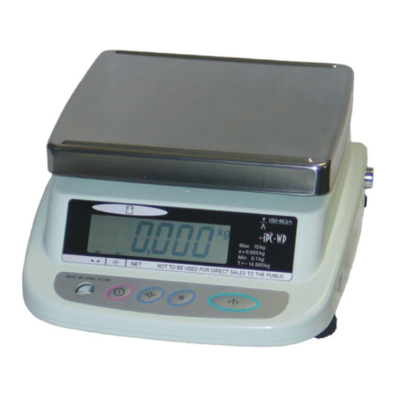
Chapter 1. Product Overview Product Overview • The IPC-WP Series is a water proof type digital scale which can be operated with two batteries. • The large LCD with 25mm height is provided for the display. Standard Specifications Item Description IPC-WP Series /IPC-WP DUAL Series Model name IPC-WP 3... - Page 7 Item Description Option AC adaptor (Dealer Option) Output voltage 3.2 to 6.0VDC (current load at 25mA, or at IPC connection) (caution) 1. Output voltage must not exceed 6.0V even if power supply voltage is at +10%. 2. Output voltage exceeds 3.2V even if power supply voltage is at -15%. Generally, AC adaptor output voltage varies with load current.
-
Page 8: Appearance
Appearance Front & Rear view Bottom view Sheet 3 Memory switch Battery cover assy Two D-sized dry Battery rubber plug batteries (option) IPC-WP Series Service Manual 5/32... -
Page 9: Operation Panel
Operation Panel ASIA Specification Oceania Specification IPC-WP Series Service Manual 6/32... - Page 10 EU Specification USA Specification IPC-WP Series Service Manual 7/32...
-
Page 11: Outer Dimensions
Outer Dimensions (Unit: mm) IPC-WP Series Service Manual 8/32... -
Page 12: Chapter 2 Test Mode
Chapter 2 Test Mode The Test Mode is used for diagnosis and/or setting at maintenance service. Test Mode Flow L003b Program No. display START C1 X Setup of country No. TARE TARE C2 XX Setup of scale No. TARE and decimal point TARE Span adjustment TARE... -
Page 13: Starting Test Mode
Key Functions (when setting value) Function Asia Oceania Use at TEST mode startup. (Press this key while the TARE key is depressed.) Use at TEST mode end Use when selecting digits. Press when fixing values after mode or data selection. Increments values for each press during data change. -
Page 14: Memory Switch
Memory Switch Operation Display 1. C mode / F mode status 2. Press the Memory Switch. C1 Mode – Country No. Setting 2.5.1 Country No. Table Country No. Wei- Item Data Digit ASIA 0: ±10% Start range 1: ±2% 0: Lights on at true zero Zero point mark 1: Lights on at Provisional zero... -
Page 15: Operation
2.5.2 Operation Operation Display 1. Stating Test 2. Setup of Country No. To select the No., use the [ * ] key Example: ASIA=2 3. When the C2 mode is then required, press the TARE key. When finishing, press the Memory Switch to record the data to the memory, and enter the Ending Test Mode. -
Page 16: Operation
2.6.3 Operation Operation Display Stating Test Scale No. and Decimal point indication mode Press the [ TARE ] key ON → (1 digit flashes) Example: ASIA 3kg (1g) Single range X1=5, X2=4 X2 X1 2.1 Scale No. Setting Press the [ * ] key ON four times ( X1=5) X2 X1 2.2 Decimal point indication Setting Press the [ ZERO ] key ON →... -
Page 17: C3 Mode - Span Adjustment
C3 Mode – Span Adjustment 2.7.1 Operation Operation Display Stating Test Span Adjustment mode 2.1 Press the TARE key ON for two times. 2.2 Press the [ * ] key ON → displays original A/D data (The normal range for original A/D data is 1000 to 25000 counts). -
Page 18: F Mode - Setting Measuring Conditions And E2Rom Clear
F Mode – Setting Measuring Conditions and E2ROM Clear • All data has been fixed according to country specifications. Note • Altering data may not conform to weighing and measuring tests for a country. • See 1.6 “C1 Mode-Country No. Setting” for Measurement Conditions Setup Reference Table. -
Page 19: Error No. List
Data after E2ROM is cleared Mode Data Item JAPAN Scale No.= 3kg (2g/1g) Multi interval Decimal point indication= " 0" Zero point and span adjustment value and each approximate value Measurement condition 2.8.2 Error No. List Error No. Mode Item Err1 At power ON E2PROM unsetting or garbled data... -
Page 20: Chapter 3 Hardware Configuration
Chapter 3 Hardware Configuration Mechanisms 3.1.1 Dual Display IPC-WP Series Service Manual 17/32... - Page 21 IPC-WP Dual Display Service Parts List Parts Name Weighing Capacity Q'ty PLATTER SHEET PROTECT PLATTER BRACKET SUS RING INSIDE AIRPROOF RUBBER RING SUS RING OUTSIDE SHEET 'DISPLAY' (---KG) Varied per country SHEET 'DISPLAY' SWITCH Varied per country PWB 'PS-022, KEY AIRPROOF SPONGE BASE PLATE SUPPORT HARNESS ,C2, GND...
-
Page 22: Single Display
3.1.2 Single Display IPC-WP Series Service Manual 19/32... - Page 23 IPC-WP Single Display Service Parts List Parts Name Weighing Capacity Q'ty PLATTER SHEET PROTECT PLATTER BRACKET SUS RING INSIDE AIRPROOF RUBBER RING SUS RING OUTSIDE SHEET 'DISPLAY' (--- KG) Varied per country SHEET 'DISPLAY' SWITCH Varied per country PWB 'PS-022, KEY AIRPROOF SPONGE BASE PLATE SUPPORT GND CORD...
-
Page 24: Electric Concerns
Electric Concerns 3.2.1 Block Diagram LOAD CELL FERRITE CORE (3 types dependi ng on w ei ghi ng capaci ty) PWB,PS-021A,MAIN FERRITE CORE PWB 'PS-019' PWB 'PS-022, KEY PWB,PS-023,DISPLAY D-size dry batteries AC adapter DUAL DISPLAY Dealer Option IPC-WP Series Service Manual 21/32... -
Page 25: Main Board Ps-021
3.2.2 Main Board PS-021 ◆ Parts side C N 4 J P 3 C N 1 C N 5 C N 6 J P 2 C N 2 J P 5 J P 6 S W 1 J P 1 J P 4 C N 3 Note: There is no grounding wire in the... - Page 26 CN6: Load cell input Pin No. Soldering land Function Remarks DC5V Approx 2.5V Approx 2.5V Jumper JP1: Ferrite cut JP2: Ferrite cut JP3: Ferrite cut JP4: Ferrite cut JP5: Filter cut JP6: Filter cut Switch SW5: E2ROM Memory switch IPC-WP Series Service Manual 23/32...
-
Page 27: Switch Board Ps-022
3.2.3 Switch Board PS-022 S W1 S W4 S W2 S W3 G Y O R BR Harness Pin No. Function Remarks tare * zero ON/OFF 3.2.4 Dual Display Board PS-023 C N 1 LC D 1 P S -0 2 3 L... -
Page 28: Chapter 4 Maintenance
Chapter 4 Maintenance Disassembly Procedure The seal restricts the peel according to the country by a no report and doing as Note wanting put it. Follow the relevant procedure for the respective countries. The water proof sheet is to maintain the water proofing property. When you remove Caution the sheet, replace it with a new one. - Page 29 6. Remove the Approval seal. Base 7. Remove the 10 M4 screws located around the base. M4 Screw Caution When re-assembling the scale, first fasten the screws tentatively, then tighten them completely one by one in a diagonal sequence. If you strongly tighten a particular point first, the Sheet water proofing property will be deteriorated (Approval seal)
-
Page 30: Main Board (Ps-021) Replacement
4.1.2 Main Board (PS-021) Replacement 1. Detach the cell cord wires by using a soldering iron. 2. Remove the screw (ST8x8). Cell cord ST8×8 3. Disconnect the power harness from the connector. Grounding cord 4. Disconnect the power display harness from the connector. -
Page 31: Customer Display Board (Ps-023) Replacement
4.1.4 Customer Display Board (PS-023) Replacement 1. Disconnect the harness from the connector. Harness ST8×8 2. Remove the screw (ST8x8). Perform this procedure in reverse for re-assembly. 4.1.5 Load Cell Replacement 1. Disconnect the cell cord wires and the grounding wires by using a soldering iron in M6×25 the same manner as for Switch Board Plate support... - Page 32 3. Remove the 4 Sheet 3s. Sheet 3 Caution When re-assembling the scale, use a new sheet protect. When affixing the new sheet protect, completely remove the starch left on the bracket. Otherwise, the water proofing property will be deteriorated. 4.
- Page 33 7. Remove the 2 Screws (M6x25) that are holding the Load cell. Load cell Load Cell 3kg: CZL-6d-C3-5kg-1000 6kg: CZL-6d-C3-10kg-1000 M6×25.SW.W Plate support 15kg: CZL-6d-C3-25kg-1000 Assembly procedure 1. Adjust the clearance limit by tightening the screw, spring washer, and flat washer on the plate support.
-
Page 34: Airproof Rubber Ring Replacement
4.1.6 Airproof Rubber Ring Replacement Caution Airproof rubber ring M4×10 If the Airproof rubber ring is damaged, make sure that there is no water-ingression in the scale. 1. Remove the 8 Screws (M4x10) on the SUS ring inside. 2. Remove the Diaphragm and SUS ring outside. -
Page 35: Troubleshooting
Troubleshooting Symptom Cause Measure • Check and replace dry batteries 1. The display check does not 1. Trouble of dry battery start when the power switch power supply system • Confirmation and exchange of battery is pushed. harness • Check output voltage (DC2.4-6.0V) 2. - Page 38 PN 86367 01/2012...
Need help?
Do you have a question about the Ishida IPC-WP Series and is the answer not in the manual?
Questions and answers