Advertisement
Available languages
Available languages
Quick Links
Dziękujemy za wybór naszego produktu.
Firma Zamel nie odpowiada za uszkodzenia oraz wypadki spowodowane niezgodnym z
przeznaczeniem użytkowaniem produktu.
Przed przystąpieniem do montażu w celu prawidłowego użytkowania należy zapoznać się
dokładnie z instrukcją obsługi.
Zabrania się otwierania oraz wszelakiej nieautoryzowanej ingerencji w urządzenie. Nie
stosowanie się do powyższego skutkuje utratą gwarancji.
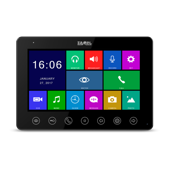
WIDEOMONITOR
VP-807B / VP-807W
Advertisement

Subscribe to Our Youtube Channel
Related Manuals for Zamel VP-807B


Summary of Contents for Zamel VP-807B
- Page 1 WIDEOMONITOR VP-807B / VP-807W Dziękujemy za wybór naszego produktu. Firma Zamel nie odpowiada za uszkodzenia oraz wypadki spowodowane niezgodnym z przeznaczeniem użytkowaniem produktu. Przed przystąpieniem do montażu w celu prawidłowego użytkowania należy zapoznać się dokładnie z instrukcją obsługi. Zabrania się otwierania oraz wszelakiej nieautoryzowanej ingerencji w urządzenie. Nie...
-
Page 2: Zawartość Zestawu
BEZPIECZEŃSTWO Należy bezwzględnie przestrzegać poniższej instrukcji dla własnego bezpieczeństwa oraz uniknięcia uszkodzenia produktu. Nie umieszczać kilku źródeł poboru prądu w jednym gnieździe równocześnie. Może to doprowadzić do przegrzania instalacji lub pożaru. Nie łączyć urządzenia z innymi niekompatybilnymi produktami. Może to doprowadzić do zwarcia a w następstwie do uszkodzenia urządzenia. - Page 3 SCHEMATY OKABLOWANIA POKÓJ 1 AD-1 CCTV1 CCTV1 DATA CCTV2 CCTV2 VD-1 PWR2 PWR1 KEY2 KEY1 PANEL 1 ELEKTROZACZEP 1 ELEKTROZACZEP 2 PANEL 2 POKÓJ 2 AD-1 CCTV1 CCTV1 DATA CCTV2 CCTV2 VD-1 PWR2 PWR1 KEY2 KEY1 POKÓJ 3 AD-1 CCTV1 CCTV1 DATA CCTV2...
- Page 4 POKÓJ 1 AD-1 CCTV1 CCTV1 DATA CCTV2 CCTV2 VD-1 CCTV3 PWR2 PWR1 KEY2 KEY1 PANEL 1 ELEKTROZACZEP 1 NC06 POKÓJ 2 AD-1 CCTV1 NIEBIESKI BIAŁY CCTV1 CZERWONY DATA ŻÓŁTY DATA NO / NC CCTV2 CCTV2 VD-1 PWR2 PWR1 KEY2 KEY1 POKÓJ 3 AD-1 CCTV1...
- Page 5 POKÓJ 1 AD-1 CCTV1 CCTV1 DATA CCTV2 CCTV2 VD-1 CCTV3 PWR2 PWR1 KEY2 KEY1 PANEL 1 POKÓJ 2 AD-1 CCTV1 CCTV1 DATA CCTV2 CCTV2 VD-1 PWR2 PWR1 KEY2 KEY1 POKÓJ 3 AD-1 CCTV1 CCTV1 DATA CCTV2 CCTV2 VD-1 PWR2 PWR1 KEY2 KEY1 POKÓJ 4...
- Page 6 Konguracja systemu Istnieje możliwość zastosowania jednej z konfiguracji systemu zgodnie ze schematami poniżej: 2 stacje bramowe + 4 wideo monitory + 2 kamery CCTV do każdego monitora MONITOR GŁÓWNY MONITOR 2 MONITOR 3 MONITOR 4 DRZWI 1 KAMERA1 KAMERA1 KAMERA1 KAMERA1 DRZWI 2 KAMERA2...
- Page 7 OPIS 1. Sygnalizacja optyczna - Led 2. Podgląd 3. Odblokowanie 4. Odpowiadanie / Zadzwonienie 5. Powrót / Odwieszenie słuchawki 6. Przycisk nawigacyjny w lewo: Wybierz / Dostosuj 7. Otwórz menu / Zatwierdź 8. Przycisk nawigacyjny w prawo: Wybierz / Dostosuj 9.
- Page 8 SPECYFIKACJA OKABLOWANIA System posiada dwa możliwe rozwiązania otwarcia elektroza czepu: sygnał otwarcia zamka z panelu rozmównego lub sygnał otwarcia zamka z monitora (ekran przewodu musi być uzie miony). W sytuacji, gdy sygnał otrzymywany jest z panelu rozmównego, specyfikacja okablowania jest następująca: Jeśli odległość...
- Page 9 ODPOWIEDŹ NA SYGNAŁ PRZYCHODZĄCY Z PANELU ROZMÓWNEGO Kiedy użytkownik (gość) naciska przycisk wywołania panelu rozmównego, wszystkie wewnętrzne monitory w obiekcie będą emitowały dźwięk jednocześnie, na ekranie zostanie wyświetlony komunikat POŁĄCZENIE PRZYCHODZĄCE. Należy kliknąć ikonę , aby rozpocząć rozmowę z gościem. Ponowne naciśnięcie przycisku spowoduje przekazanie obrazu na pozostałe monitory.
- Page 10 zostanie wyświetlony komunikat ROZGŁASZANIE – można przystąpić do rozgłaszania informacji. Naciśnięcie przycisku zatrzymuje rozgłaszanie. POŁĄCZENIA INTERKOMOWE Stosowane w celu połączenia interkomowego (wewnętrznego) do wszystkich monitorów. W trybie gotowości, kliknąć ikonę aby połączyć się z innym monitorem. Jeśli posiadamy więcej niż 2 monitory połączone ze sobą w systemie, można wybrać...
- Page 11 USTAWIENIA SYSTEMOWE , aby przejść do menu ustawień W trybie gotowości, wybrać przycisk systemowych. Funkcje systemu Opcje Uwagi JĘZYK Ustawienie fabryczne: j. polski (opcjonalnie język angielski) Ustawienie fabryczne: 30 sekund (10-60 sekund- możliwość CZAS SYGNAŁU zmiany co 5s) Ustawienie fabryczne: 0,7, 01-10 możliwość regulacji. (00) oznacza GŁOŚNOŚC SYGNAŁU wyciszenie.
-
Page 12: Ustawienia Zaawansowane
źródła zasilania (baterie), będące na wyposażeniu urządzenia w momencie jego sprzedaży (jeśli występują). 3. Wszelkie roszczenia z tytułu gwarancji KUPUJĄCY zgłosi w punkcie zakupu lub firmie ZAMEL Sp. z o.o. na piśmie po ich stwierdzeniu. 4. ZAMEL Sp. z o.o. zobowiązuje się do rozpatrywania reklamacji zgodnie z obowiązującymi przepisami prawa polskiego. - Page 13 VP-807B / VP-807W Thank you for buying this product from Zamel. Zamel shall not accept any liability for any results of damage and/or accidents caused by non-intended use of the product. Before attempting installation of this product, read and understand its entire Operating Manual to comply with the intended use.
-
Page 14: Technical Specifications
SAFETY Always follow this Manual for your safety and to prevent damage to the product. Do not connect more than one load to a single power outlet at a time. Risk of overheating the wiring or fire! Do not connect or interface this device with incompatible products. Otherwise, a risk of electrical short circuit may occur, resulting in damage of this product. - Page 15 WIRING CONNECTION DIAGRAM AD: Audio VD: Video PWR: Power GND: Ground: DATA: Communication CCTV: CCTV feed in KEY1/KEY2: Control voltage Tekst Translation POKÓJ 1 ROOM 1 ELEKTROZACZEP 1 ELECTRIC STRIKE NO. 1 PANEL 1 PANEL 1...
- Page 16 AD: Audio VD: Video PWR: Power GND: Ground: DATA: Communication CCTV: CCTV feed in KEY1/KEY2: Control voltage Tekst Translation ELEKTROZACZEP 1 ELECTRIC STRIKE NO. 1 NIEBIESKI BLUE ŻÓŁTY YELLOW BIAŁY WHITE CZERWONY Note: (a) Wiring connection diagram for an entrance panel with electric strike no. 2 + extra external power supply.
- Page 17 AD: Audio VD: Video PWR: Power GND: Ground: DATA: Communication CCTV: CCTV feed in KEY1/KEY2: Control voltage • The 2nd and each additional display may only output the video feeds from the cameras they are connected to. • All displays can output the video feed of a CCTV camera connected to the entrance panel port.
- Page 18 System configuration The system can be installed in one of the configurations shown in the diagrams below: • 2 gate entrance panels + 4 displays + 2 CCTV cameras for each display Tekst Translation MONITOR GŁÓWNY MAIN DISPLAY MONITOR 2 DISPLAY 2 DRZWI 1 DOOR 1...
- Page 19 DESCRIPTION 1. LED indicator 2. Video feed display 3. Unlock 4. Answer / Call 5. Back / Hang Up 6. Left arrow button: Select / Adjust 7. Enter Menu / Confirm 8. Right arrow button: Select / Adjust 9. Microphone 10.
- Page 20 WIRING SPECIFICATIONS The system supports two electric strike release configurations: with the open command output by (i) an entrance panel or (ii) a system display (the display open command output wire must have the shield connected to earth). If the open command is output by an entrance panel, follow this wiring specification: ...
- Page 21 ANSWERING AN ENTRANCE PANEL CALL When a visitor presses the Call button on the entrance panel, all connected indoor displays will sound the call chime at the same time with the INCOMING CALL message on each display screen. Touch the icon to answer the call.
- Page 22 INTERNAL CALLS (DISPLAY-TO-DISPLAY INTERCOM MODE) The intercom mode allows two-way voice calls between two specific displays in the video entry phone system. Touch on the display in standby to call another display in the system. If you have more than 2 displays in the video entry phone system, choose the display you wish to call with .
-
Page 23: System Settings
SYSTEM SETTINGS With the display in standby, touch and open the System Settings menu. Item System functions Options Notes LANGUAGE Default setting: PL (Polish) (optional: EN for English). RING TIME Default setting: 30 s (10 to 60 s, adjustable in 5 s steps). Default setting: 0.7, adjustable in a 01-10 range. -
Page 24: Warranty
(batteries) included (if any) with the device as sold. 3. The BUYER shall submit all warranty claims in writing to the original reseller or to ZAMEL Sp. z o.o. 4. ZAMEL Sp. z o.o. will examine each warranty claim as regulated by the applicable provisions of the Polish law. - Page 25 VP-807B/VP-807W Wir bedanken uns für den Kauf unseres Produkts und Ihr entgegengebrachtes Vertrauen. Die Firma Zamel haftet nicht für Beschädigungen und Unfälle, die aus unsachgemäßem Betrieb oder unsachgemäßer Nutzung resultieren. Lesen Sie vor der Montage die Betriebsanleitung aufmerksam durch und befolgen Sie die Anweisungen sorgfältig.
- Page 26 SICHERHEITSVORKEHRUNGEN Für persönliche Sicherheit und zur Vermeidung von Produktschäden befolgen Sie die Betriebsanleitung sorgfältig. Meiden Sie den Anschluss an einer Mehrfachsteckdose – Überhitzungs- oder Brandgefahr. Der Anschluss mit nicht kompatiblen Geräten ist nicht gestattet – Kurzschlussgefahr und anschließend Beschädigung des Geräts.
-
Page 27: Technische Daten
BESCHREIBUNG LIEFERUMFANG 7ʺ LCD Farbdisplay 1 x Videomonitor Installation: 4- Draht – System 1 x Bedienungsanleitung Intuitive Menüführung 1 x Halterung (Basis) Interne Kommunikation möglich 2 x Montagedübel Broadcast-Funktion 2 x M4 x 30 Schrauben ... - Page 28 VERKABELUNGSSCHEMEN AD: Audio VD: Video PWR: Versorgungsspannung GND: Erdung DATA: Kommunikation CCTV: CCTV-Kamera KEY1/KEY2: Spannungsregelung Tekst Übersetzung POKÓJ 1 RAUM 1 ELEKTROZACZEP 1 TÜRÖFFNER 1 PANEL 1 ELEMENT 1...
- Page 29 AD: Audio VD: Video PWR: Versorgungsspannung GND: Erdung DATA: Kommunikation CCTV: CCTV-Kamera KEY1/KEY2: Spannungsregelung Tekst Übersetzung ELEKTROZACZEP 1 TÜRÖFFNER 1 NIEBIESKI BLAU ŻÓŁTY GELB BIAŁY WEISS CZERWONY Hinweis: (a) Anschluss des Außenelements mit dem Türöffner Nr. 2 + zusätzliche Außenversorgung. (b) Anschluss des Türöffners Nr.
- Page 30 AD: Audio VD: Video PWR: Versorgungsspannung GND: Erdung DATA: Kommunikation CCTV: CCTV-Kamera KEY1/KEY2: Spannungsregelung • Die Livebild Aufnahme erfolgt ausschließlich, sobald der Videomonitor mit der CCTV- Kamera verbunden ist. • Die Livebild Aufnahmen können von allen Videomonitoren angezeigt werden, solange die CCTV- Kamera mit dem Außenelement verbunden ist.
- Page 31 Systemkonfiguration Sie können zwischen zwei verschiedenen Konfigurationsvarianten auswählen: • 2 Außenelemente + 4 Videomonitore + 2 CCTV-Kameras pro Videomonitor Tekst Übersetzung MONITOR GŁÓWNY HAUPTMONITOR MONITOR 2 MONITOR 2 DRZWI 1 TÜR 1 KAMERA1 KAMERA1 • 1 Außenelement + 1 CCTV-Kamera + 4 Videomonitore + 2 CCTV- Kameras pro Videomonitor...
- Page 32 BESCHREIBUNG 1. Optisches Signal - LED 2. Livebild 3. Freigabe 4. Antworten / Anrufen 5. Zurück / Ablegen 6. Navigationstaste links: Auswählen / Anpassen 7. Menü öffnen / Übernehmen 8. Navigationstaste rechts: Auswählen / Anpassen 9. Mikrofon 10. Einschalten\ausschalten 11. LCD-Bildschirm MONTAGE 1.
- Page 33 KABELSPEZIFIKATION Das System verfügt über zwei Möglichkeiten, den Türöffner auszulösen: Ein vom Außenelement kommendes Signal öffnet den Türöffner oder ein vom Videomonitor kommendes Signal öffnet den Türöffner (die Leiterummantelung muss geerdet sein). Falls das Signal vom Außenelement kommt, ändert sich die Kabelspezifikation wie folgt: ...
- Page 34 Verwenden Sie das Kabel YTDY 6 x 0,5, falls die Kabelverbindung zwischen Videomonitor und Außenelement 30 m unterschreitet. Verwenden Sie das KABEL YTDY 6 x 0,8, falls die Kabelverbindung zwischen Videomonitor und Außenelement 30 m überschreitet...
- Page 35 DEM RUFSIGNAL VOM AUSSENELEMENT ANTWORTEN Sobald der Benutzer (Gast) die Klingeltaste drückt, ertönt ein Klingelton. Der Anruf wird auf allen Videomonitoren angezeigt. Auf dem Display erscheint die Mitteilung EINGEHENDER ANRUF. Drücken Sie die Taste , um den Anruf entgegen zu nehmen. Erneutes Drücken der Taste bewirkt eine Bildübertragung auf die restlichen Videomonitore.
- Page 36 ÜBERTRAGEN BZW. ÜBERMITTELN. Das Drücken der Taste stoppt die Spracheingabe. INTERCOM-FUNKTION Dient dazu, die (interne) Intercom-Verbindung zu allen Monitoren herzustellen. Drücken Sie im Standby-Modus die Taste , um eine Verbindung zum Videomonitor herzustellen. Wählen Sie einen Zielmonitor aus, falls Sie mehr als 2 Videomonitore verbaut haben.
- Page 37 SYSTEMEINSTELLUNGEN Drücken Sie die Taste und anschließend die Taste , um die Systemeinstellungen aufzurufen. Funktionen Optionen Bemerkungen SPRACHE Werkseitig: Polnisch (optional Englisch) Werkseitig: 30 Sekunden (10-60 Sekunden mit Verstellung in SIGNALZEIT 5s-Schritten) SIGNALLAUTSTÄRKE Werkseitig: 0,7, 01-10 einstellbar. (00) stummgeschaltet. Werkseitig ist die Funktion bei Aufruf, Intercom, Broadcast PRIVATFUNKTION deaktiviert.
-
Page 38: Garantie
3. Der KÄUFER ist verpflichtet, sämtliche Garantieansprüche nach deren Feststellung dem Verkäufer oder der Firma ZAMEL Sp. z o.o. schriftlich zu melden. 4. ZAMEL Sp. z o.o. verpflichtet sich, die Reklamationen nach den geltenden Vorschriften des polnischen Rechts zu prüfen.
Need help?
Do you have a question about the VP-807B and is the answer not in the manual?
Questions and answers