Table of Contents
Advertisement
Quick Links
VIDEO ENTRY PHONE DISPLAY
VP-816B / VP-816W
Thank you for buying this product from Zamel.
Zamel shall not accept any liability for any results of damage and/or accidents
caused by non-intended use of the product.
Before attempting to install this product, please read and understand the entire
Operating Manual to comply with the intended use.
Do not open or tamper with the product without prior authorization. Otherwise your
warranty rights for this product will be void.
Advertisement
Table of Contents

Related Manuals for Zamel VP-816B


Summary of Contents for Zamel VP-816B
- Page 1 VP-816B / VP-816W Thank you for buying this product from Zamel. Zamel shall not accept any liability for any results of damage and/or accidents caused by non-intended use of the product. Before attempting to install this product, please read and understand the entire Operating Manual to comply with the intended use.
-
Page 2: Product Description
SAFETY • Always follow this Manual for your safety and to prevent damage to the product. • Do not connect more than one load to a single power outlet at a time. Risk of overheating the wiring or fire! • Do not connect or interface this device with incompatible products. Otherwise there is a risk of an electrical short circuit, resulting in damage to this product. -
Page 3: Wiring Connection Diagram
WIRING CONNECTION DIAGRAM ROOM 1 DISPLAY 1 DISPLAY 2 ELECTRIC ELECTRIC CATCH 1 CATCH 2 ROOM 2 ROOM 3 ROOM 4 AD: Audio VD: Video PWR: Power GND: Ground DATA: Data communication CCTV: CCTV feed in KEY1/KEY2: Control voltage... - Page 4 ROOM 1 ELECTRIC DISPLAY 1 CATCH 1 ROOM 2 BLUE WHITE YELLOW ROOM 3 ROOM 4 AD: Audio VD: Video PWR: Power GND: Ground DATA: Data communication CCTV: CCTV feed in KEY1/KEY2: Control voltage Note: (a) Wiring connection diagram for an entrance panel with electric catch no.
- Page 5 ROOM 1 DISPLAY 1 ROOM 2 ROOM 3 ROOM 4 AD: Audio VD: Video PWR: Power GND: Ground DATA: Data communication CCTV: CCTV feed in KEY1/KEY2: Control voltage • The second and each additional display may only output the video feeds from the cameras to which they are connected.
-
Page 6: System Configuration
SYSTEM CONFIGURATION The system can be installed in one of the configurations shown in the diagrams below: • 2 gate entrance panels + 4 displays + 2 CCTV cameras for each display MAIN DISPLAY DISPLAY 2 DISPLAY 3 DISPLAY 4 DOOR 1 CAMERA 1 CAMERA 1... -
Page 7: Installing The System
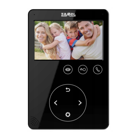
PRODUCT DESCRIPTION 1. Power On/Off switch 2. Enter Menu / Confirm 3. Speaker 4. Left arrow button: Select / Adjust 5. Back / Hang Up 6. LED indicator 7. LCD 8. Microphone 9. Video feed display 10. Unlock electric catch / gate 11. -
Page 8: Wiring Specifications
WIRING SPECIFICATIONS The system supports two electric catch release configurations: with the open command sent by (i) an entrance panel or (ii) a system display (the display open command output wire must have the shield connected to earth). If the open command is sent by an entrance panel, use this wiring specification: If the entrance panel is <... -
Page 9: Public Address Mode
ANSWERING AN ENTRANCE PANEL CALL When a visitor presses the Call button on the entrance panel, all connected indoor displays will sound the call chime at the same time as the INCOMING CALL message on each display screen. Touch the icon to answer the call. -
Page 10: Do Not Disturb Mode
INTERNAL CALLS (DISPLAY-TO-DISPLAY INTERCOM MODE) The intercom mode allows two-way voice calls between two specific displays in the video entry phone system. Touch on the display on standby to call another display in the system. If you have more than 2 displays in the video entry phone system, choose the display you wish to call with . -
Page 11: System Settings
SYSTEM SETTINGS With the display on standby, touch and open the System Settings menu. Item System functions Options Note LANGUAGE Default setting: PL (Polish) (optional: EN for English). RING TIME Default setting: 30 s (10 to 60 s, adjustable in 5 s steps). Default setting: 0.7, adjustable in the 01-10 range. -
Page 12: Warranty
3. The BUYER shall make all warranty claims in writing at the point of sale or to ZAMEL Sp. z o.o. 4. ZAMEL Sp. z o.o. will examine each warranty claim as regulated by the applicable provisions of the Polish law.
Need help?
Do you have a question about the VP-816B and is the answer not in the manual?
Questions and answers