Table of Contents
Advertisement
Quick Links
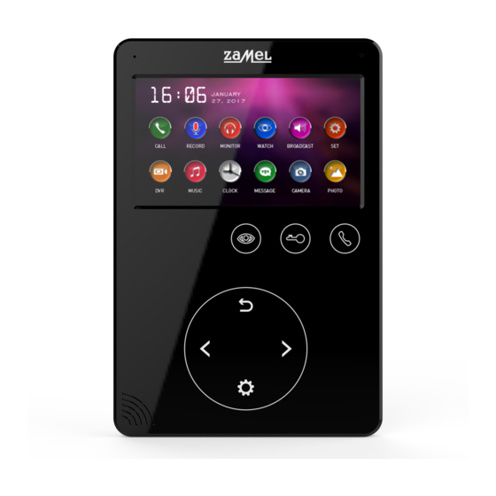
VIDEO ENTRY PHONE DISPLAY
VP-817B / VP-817W
Thank you for buying this product from Zamel.
Zamel shall not accept any liability for any results of damage
and/or accidents caused by non-intended use of the product.
Before attempting installation of this product, please read and understand
the entire Operating Manual to comply with the intended use.
Do not open or tamper with the product without prior authorization.
Otherwise your warranty rights for this product will be void.
Advertisement
Table of Contents

Related Manuals for Zamel VP-817B


Summary of Contents for Zamel VP-817B
- Page 1 VP-817B / VP-817W Thank you for buying this product from Zamel. Zamel shall not accept any liability for any results of damage and/or accidents caused by non-intended use of the product. Before attempting installation of this product, please read and understand the entire Operating Manual to comply with the intended use.
-
Page 2: Product Description
SAFETY • Always follow this Manual for your safety and to prevent damage to the product. • Do not connect more than one load to a single power outlet at a time. Risk of overheating the wiring or fire! • Do not connect or interface this device with incompatible products. Otherwise there is a risk of an electrical short circuit, resulting in damage to this product. -
Page 3: Technical Data
• On-demand video feed monitoring from entrance panels and all connected CCTV cameras • Two-way voice communication • High display screen resolution: 800 x 480 • Clear voice handset-free device • 10-step voice volume control • 10-step brightness, contrast and saturation control •... -
Page 4: Wiring Connection Diagram
WIRING CONNECTION DIAGRAM ROOM 1 DISPLAY 1 ELECTRIC DISPLAY 2 ELECTRIC CATCH 1 CATCH 2 ROOM 2 ROOM 3 ROOM 4 AD: Audio VD: Video PWR: Power GND: Ground DATA: Data communication CCTV: CCTV feed in KEY1/KEY2: Control voltage... - Page 5 ROOM 1 ELECTRIC DISPLAY 1 CATCH 1 ROOM 2 BLUE WHITE YELLOW ROOM 3 AD: Audio ROOM 4 VD: Video PWR: Power GND: Ground DATA: Data communication CCTV: CCTV feed in KEY1/KEY2: Control voltage Note: (a) Wiring connection diagram for an entrance panel with electric catch no.
- Page 6 ROOM 1 DISPLAY 1 ROOM 2 ROOM 3 ROOM 4 AD: Audio VD: Video PWR: Power GND: Ground DATA: Data communication CCTV: CCTV feed in KEY1/KEY2: Control voltage • The second and each additional display may only output the video feeds from the cameras to which they are connected.
-
Page 7: System Configuration
SYSTEM CONFIGURATION The system can be installed in one of the configurations shown in the diagrams below: • 2 gate entrance panels + 4 displays + 2 CCTV cameras for each display MAIN DISPLAY DISPLAY 2 DISPLAY 3 DISPLAY 4 CAMERA 1 CAMERA 1 CAMERA 1... -
Page 8: Installing The System
PRODUCT DESCRIPTION 1. Power On / Off switch 2. Enter Menu / Confirm 3. Speaker 4. Left arrow button: Select / Adjust 5. Back / Hang Up 6. LED indicator 7. LCD 8. Microphone 9. Video feed display 10. Unlock electric catch / gate 11. -
Page 9: Wiring Specifications
WIRING SPECIFICATIONS The system supports two electric catch release configurations: with the open command sent by (i) an entrance panel or (ii) a system display (the display open command output wire must have the shield connected to earth). If the open command is sent by an entrance panel, use this wiring specification: •... -
Page 10: Menu Overview
MENU OVERVIEW PRZEGLĄD MENU When the display is in the sleep mode, press to open the menu W trybie czuwania nacisnąć przycisk w celu aktywowania menu poniżej: shown below: 16:06 JANUARY 27,2017 CALL MONITOR BROADCAST RECORD WATCH MUSIC CLOCK MESSAGE CAMERA PHOTO Item... -
Page 11: Public Address Mode
ANSWERING AN ENTRANCE PANEL CALL When a visitor presses the Call button on the entrance panel, all connected indoor displays will sound the call chime at the same time as displaying the INCOMING CALL message on each display screen. Touch the icon to answer the call. - Page 12 INTERNAL CALLS (DISPLAY-TO-DISPLAY INTERCOM MODE) The intercom mode allows two-way voice calls between two specific displays in the video entry phone system. Touch on the display on standby to call another display in the system. If you have more than 2 displays in the video entry phone system, choose the display you wish to call with .
-
Page 13: Snapshot Capture
DISPLAY MICROPHONE MONITORING ODSŁUCHIWANIE INNEGO MONITORA With the display on standby, touch and hold to start listening through W trybie gotowości, należy przytrzymać ikonę aby przejść do funkcji the microphone of another display in the voice entry phone system. If you have odsłuchiwania innego monitora. - Page 14 LEAVE MESSAGE MODE The mode allows each visitor to leave a voice message with the entrance panel when no one answers the call. Activate the mode by setting AUTO LEAVING MESSAGE to Enable in the System Settings. When the Leave Message mode is active, the caller at an entrance panel will hear a recorded Away-from-Home Reply if they press the Call button and the call chime ends unanswered.
- Page 15 Funkcje systemu Opcje Uwagi ILOŚĆ AUTOMATYCZNE Automatycznie przechwytuje 1, 2 lub 3 PRZECHWYTYWANYCH 01, 02, 03 zdjęcia podczas wywołania. ZDJĘĆ Można pozostawić wiadomość po The visitor calling with an entrance panel AUTOMATYCZNE WŁĄCZONE ENABLE can leave a voice message after usłyszeniu tonu.
-
Page 16: Dvr Settings
VIDEO SNAPSHOT CAPTURE SETTINGS Storage type Resolution Number of snapshots 640 x 480 / 320 x 240, Embedded flash memory 100 snapshots max. as set in Resolution Depends 640 x 480 / 320 x 240, microSD card on the microSD card as set in Resolution capacity DVR RECORDING SETTINGS... -
Page 17: Alarm Clock
ALARM CLOCK ALARM ZEGAROWY Touch in the Main Menu. Touch , and touch to open the Alarm Clock Nacisnąć przycisk w menu głównym, wybrać następnie przyciskając settings. wejść do ustawieni Alarmu Zegarowego. Opcje Ustawienia Uwagi Item Settings Options Note USTAWIENIA Godzina/Minuta/ Hour / Minutes / CZASU... -
Page 18: Chime Settings
DŹWIĘK ALARMU ZAWSZE AKTYWNY PRZEZ 1 MINUTĘ O USTAWIONEJ 1/2/3/4 GODZINIE ALARMUJE W USTAWIONE DNI AKTYWNY W PRZEZ 1 MINUTĘ O USTAWIONEJ OKREŚLONE DNI GODZINIE CHIME SETTINGS USTAWIENIA DZWONKA Nacisnąć przycisk w menu głównym, wybrać następnie przyciskając Touch in the Main Menu. Touch , and touch to open the Chime settings. -
Page 19: Advanced Settings
3. The BUYER shall make all warranty claims in writing at the point of sale or to ZAMEL Sp. z o.o. 4. ZAMEL Sp. z o.o. will examine each warranty claim as regulated by the applicable provisions of the Polish law.
Need help?
Do you have a question about the VP-817B and is the answer not in the manual?
Questions and answers