Sign In
Upload
Manuals
Brands
WAGO Manuals
Control Unit
750-633
WAGO 750-633 Manuals
Manuals and User Guides for WAGO 750-633. We have
1
WAGO 750-633 manual available for free PDF download: Manual
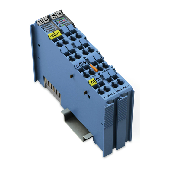
WAGO 750-633 Manual (66 pages)
Up/Down Counter Ex i for WAGO-I/O-SYSTEM 750
Brand:
WAGO
| Category:
Control Unit
| Size: 2 MB
Table of Contents
Table of Contents
3
1 Notes about this Documentation
5
Validity of this Documentation
5
Copyright
5
Symbols
6
Number Notation
8
Font Conventions
8
Table 1: Number Notation
8
Table 2: Font Conventions
8
2 Important Notes
9
Legal Bases
9
Subject to Changes
9
Personnel Qualifications
9
Use of the WAGO-I/O-SYSTEM 750 in Compliance with Underlying Provisions
9
Technical Condition of Specified Devices
10
Safety Advice (Precautions)
11
3 Device Description
13
View
15
Figure 1: View
15
Table 3: Legend for Figure "View
15
Connectors
16
Data Contacts/Internal Bus
16
Figure 2: Data Contacts
16
Power Jumper Contacts/Field Supply
17
Figure 3: Power Jumper Contacts
17
Table 4: Legend for Figure "Power Jumper Contacts
17
CAGE CLAMP ® Connectors
18
Figure 4: CAGE CLAMP ® Connectors
18
Table 5: Legend for Figure "CAGE CLAMP ® Connectors
18
Display Elements
19
Operating Elements
19
Figure 5: Display Elements
19
Table 6: Legend for Figure "Display Elements
19
Schematic Diagram
20
Figure 6: Schematic Diagram
20
Technical Data
21
Device Data
21
Supply
21
Communication
21
Table 7: Technical Data - Device
21
Table 8: Technical Data - Supply
21
Table 9: Technical Data - Communication
21
Counter
22
Inputs
22
Outputs
22
Table 10: Technical Data - Counter
22
Table 11: Technical Data - Inputs
22
Table 12: Technical Data - Outputs
22
Explosion Protection Inputs
23
Table 13: Technical Data - Explosion Protection Inputs
23
Explosion Protection Outputs
24
Connection Type
24
Table 14: Technical Data - Explosion Protection Outputs
24
Table 15: Technical Data - Field Wiring
24
Table 16: Technical Data - Power Jumper Contacts
24
Climatic Environmental Conditions
25
Table 17: Technical Data - Data Contacts
25
Table 18: Technical Data - Climatic Environmental Conditions
25
Approvals
26
Standards and Guidelines
28
4 Process Image
30
Operating Mode 1 - up Counter with Enable Input and Operating Mode 2 - Up/Down Counter with U/D Input
30
Table 19: Process Image, Operating Mode 1/2
30
Table 20: Control Byte C0, Operating Mode 1/2
30
Set Counter
31
Disable Counter
31
Set Output
31
Example
31
Table 21: Status Byte S0, Operating Mode 1/2
31
Operating Mode 3 - Frequency Counter
33
Table 22: Process Image, Operating Mode 3
33
Table 23: Control Byte C0, Operating Mode 3
33
Table 24: Status Byte S0, Operating Mode 3
33
Set Measuring Method, Frequency Range and Measured Value Display
34
Set Watchdog Time
34
Table 25: Measuring Method, Frequency Range and Measured Value Display Settings
34
Set Output
35
Example
35
Operating Mode 4 - Peak-Time Counter
36
Set Output
36
Table 26: Process Image, Operating Mode 4
36
Table 27: Control Byte C0, Operating Mode 4
36
Table 28: Status Byte S0, Operating Mode 4
36
Example
37
5 Mounting
39
Mounting Sequence
39
Inserting and Removing Devices
40
Inserting the I/O Module
40
Figure 7: Insert I/O Module (Example)
40
Figure 8: Snap the I/O Module into Place (Example)
40
Removing the I/O Module
41
Figure 9: Removing the I/O Module (Example)
41
6 Connect Devices
42
Connecting a Conductor to the CAGE CLAMP
42
Figure 10: Connecting a Conductor to a CAGE CLAMP
42
Power Supply Concept
43
Figure 11: Supply Principle Ex I
44
Figure 12: Overvoltage Categories
44
Table 29: Legend for Figure "Overvoltage Categories
44
Power Supply Concept in Marine Applications
45
Figure 13: Power Supply Concept, Category EMC1 (Marine Applications)
45
Table 30: Legend for Figure "Power Supply Concept, Category EMC1
45
Figure 14: Power Supply Concept, Category EMC2 (Marine Applications)
46
Table 31: Legend for Figure "Power Supply Concept, Category EMC2
46
Connection Example
47
Figure 15: Connection Example for U/D (GATE), CLK and DO
47
7 Parameterizing
48
Parameterization with WAGO-I/O-CHECK
48
Up/Down Counter Ex I 750-633 (Parameter Dialog Box)
48
Figure 16: Up/Down Counter Ex I 750-633 (Parameter Dialog Box)
48
Up/Down Counter Ex I 750-633 Toolbar
49
Figure 17: Up/Down Counter Ex I 750-633 Toolbar
49
Table 32: Up/Down Counter Ex I 750-633 Toolbar
49
Up/Down Counter Ex I 750-633 Parameter
50
Figure 18: Up/Down Counter Ex I 750-633 Parameter
50
Table 33: Up/Down Counter Ex I 750-633 Parameter
50
8 Use in Hazardous Environments
51
Marking Configuration Examples
52
Marking for Europe According to ATEX and Iecex
52
Figure 19: Marking Example According to ATEX and Iecex
52
Figure 20: Text Detail - Marking Example According to ATEX and Iecex
52
Table 34: Description of Marking Example According to ATEX and Iecex
53
Figure 21: Marking Example for Approved Ex I I/O Module According to ATEX and Iecex
54
Figure 22: Text Detail - Marking Example for Approved Ex I I/O Module According to ATEX and Iecex
54
Table 35: Description of Marking Example for Approved Ex I I/O Module According to ATEX and Iecex
55
Table 37: Description of Marking Example for Approved Ex I I/O Module
55
Marking for America (NEC) and Canada (CEC)
56
Figure 23: Marking Example According to NEC
56
Figure 24: Text Detail - Marking Example According to NEC 500
56
Table 36: Description of Marking Example According to NEC 500
56
Figure 25: Text Detail - Marking Example for Approved Ex I I/O Module
57
Figure 26: Text Detail - Marking Example for Approved Ex I I/O Module
57
Table 38: Description of Marking Example for Approved Ex I I/O Modules
57
Figure 27: Text Detail - Marking Example for Approved Ex I I/O Modules
58
Table 39: Description of Marking Example for Approved Ex I I/O Modules
58
Installation Regulations
59
Special Notes Regarding Explosion Protection
59
Special Notes Regarding ANSI/ISA Ex
61
9 Appendix
62
Rated Surge Voltage
62
Table 40: Rated Surge Voltage *)
62
List of Figures
63
List of Tables
64
Advertisement
Advertisement
Related Products
WAGO 750-638
WAGO 750-637
WAGO 750-637/000-001
WAGO 750-637/000-002
WAGO 750-637/000-004
WAGO 750-632
WAGO 750-632/000-100
WAGO 750-645
WAGO 750-606/040-000
WAGO 750-624/020-002
WAGO Categories
I/O Systems
Control Unit
Power Supply
Switch
Controller
More WAGO Manuals
Login
Sign In
OR
Sign in with Facebook
Sign in with Google
Upload manual
Upload from disk
Upload from URL