Samson TROVIS 5757-3 Mounting And Operating Instructions
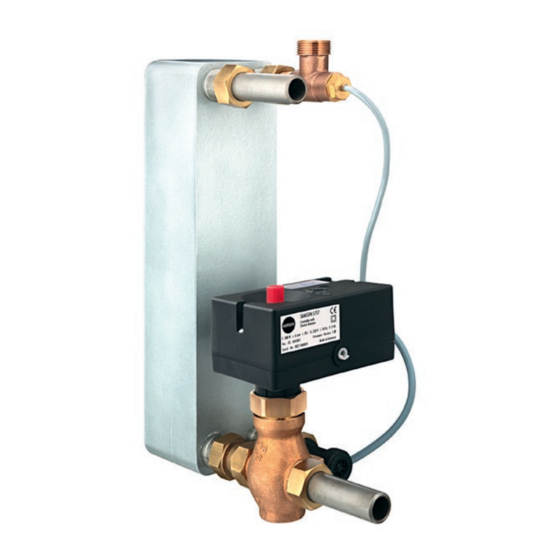
Electric actuator with process controller for domestic hot water heating
Hide thumbs
Also See for TROVIS 5757-3:
- Mounting and operating instructions (32 pages) ,
- Configuration manual (24 pages)

Related Manuals for Samson TROVIS 5757-3


Summary of Contents for Samson TROVIS 5757-3
- Page 1 EB 5757 EN Translation of original instructions TROVIS 5757-3 Electric Actuator with Process Controller for domestic hot water heating Firmware version 2.20 Edition September 2016...
- Page 2 Note on these mounting and operating instructions These mounting and operating instructions assist you in mounting and operating the device safely. The instructions are binding for handling SAMSON devices. The images shown in these instructions are for illustration purposes only. The actual product may vary.
-
Page 3: Table Of Contents
Contents Safety instructions and measures ..............1-1 Notes on possible severe personal injury ............1-4 Notes on possible personal injury ..............1-4 Notes on possible property damage .............1-5 Markings on the device ................2-1 Nameplate ....................2-1 Firmware versions ..................2-2 Design and principle of operation ...............3-1 Communication ..................3-3 Technical data ....................3-4 Dimensions ....................3-5... - Page 4 Malfunctions ....................9-1 Troubleshooting ..................9-1 Error indication by LEDs ................9-2 Emergency action ..................9-3 Servicing....................10-1 Decommissioning ..................11-1 Removal ....................12-1 Repairs ....................13-1 13.1 Returning the actuator to SAMSON ............13-1 Disposal ....................14-1 Certificates ....................15-1 Annex......................16-1 16.1 Accessories ....................16-1 16.2 After-sales service ..................16-2 16.3 Configuration list..................16-3 16.4...
-
Page 5: Safety Instructions And Measures
Therefore, operators must ensure that the actuator is only used in operating conditions that meet the specifications used for sizing the actuator at the ordering stage. In case operators intend to use the actuator in other applications or conditions than specified, contact SAMSON. SAMSON does not assume any liability for damage resulting from the failure to use the de- vice for its intended purpose or for damage caused by external forces or any other external factors. Î Refer to the technical data for limits and fields of application as well as possible uses. See the 'Design and principle of operation' section. - Page 6 Î Check with the plant operator for details on further protective equipment. Revisions and other modifications Revisions, conversions or other modifications of the product are not authorized by SAMSON. They are performed at the user's own risk and may lead to safety hazards, for example. Fur- thermore, the product may no longer meet the requirements for its intended use.
- Page 7 The electric actuator with process controller is designed for use in low-voltage installations. Î For wiring, maintenance and repair, observe the relevant safety regulations. Referenced documentation The documentation for the TROVIS 5757-3 Electric Actuator with Process Controller consists of the Mounting and Operating Instructions EB 5757 and the Configuration Manual u KH 5757.
-
Page 8: Notes On Possible Severe Personal Injury
Safety instructions and measures 1.1 Notes on possible severe personal injury DANGER Risk of fatal injury due to electric shock. Î Before connecting wiring and performing any work on the device, disconnect the supply voltage and protect it against unintentional reconnection. Î... -
Page 9: Notes On Possible Property Damage
Risk of actuator damage due to the supply voltage exceeding the permissible toler- ances. The TROVIS 5757-3 Electric Actuator with Process Controller is designed for use ac- cording to regulations for low-voltage installations. Î Observe the permissible tolerances of the supply voltage. - Page 10 EB 5757 EN...
-
Page 11: Markings On The Device
Markings on the device 2 Markings on the device 2.1 Nameplate TROVIS 5757-3 Electric Actuator with Process Controller Var.-ID xxxxxxx Serial no. xxxx *xxxxxx* F: 300 N s: 6 mm v: 0.3 mm/s Firmware: 2.xx U: 230 V f: 50 Hz... -
Page 12: Firmware Versions
Markings on the device 2.2 Firmware versions Firmware revisions 1.0x 2.0x/2.1x Additional features: − Switching output (see Annex). − Data logging function (see Configuration Manual u KH 5757). − Command mode (see Configuration Manual u KH 5757). 2.0x/2.1x 2.20 Extension of function of switching output (F16) to additional setting option "Circulation pump (heating) reversed" (see Annex and Configuration Manual u KH 5757). New pump protection function (F17) (see Annex and Configuration Manual u KH 5757). EB 5757 EN... -
Page 13: Design And Principle Of Operation
(7). When the actuator stem retracts, the valve is opened as ation the plug stem (6) follows the motion of the The TROVIS 5757-3 Electric Actuator with return spring. Process Controller is an electric actuator with When connected to a three-way mixing an integrated digital controller. - Page 14 Design and principle of operation set point controller with this input. Alterna- tively, the electric actuator can be used for domestic hot water in instantaneous heating system. In this case, either a water flow sen- sor or a flow switch must be used for fast de- tection. The flow switch recognizes when the hot water is being tapped. The water flow sensor can additionally record the quantity of hot water being tapped. An optimization function adapts the control to the changing network conditions.
-
Page 15: Communication
Design and principle of operation 3.1 Communication Serial interface The actuator is fitted with an RS-232 serial interface. This allows communication with TROVIS-VIEW using SSP protocol. Configuration The actuator is configured using the TROVIS- VIEW software that enables the user to easily configure the controller as well as view process parameters online. Note TROVIS-VIEW can be downloaded free of charge from our website at u www.samsongroup.com >... -
Page 16: Technical Data
Design and principle of operation 3.2 Technical data Table 3-1: Technical data · TROVIS 5757-3 TROVIS 5757-3 Connection to valve Force-locking Rated travel 6 mm Manual override Transit time for rated travel 20 s Thrust 300 N Supply voltage 230 V (±10 %), 50 Hz Power consumption Approx. 4 VA Sensor input Pt 1000... -
Page 17: Dimensions
Design and principle of operation 3.3 Dimensions Ø 12 Fig. 3-3: Dimensions in mm · Electric actuator with process controller EB 5757 EN... - Page 18 Design and principle of operation Ø5.4 Ø3.3 Type 5207-0060 Pt 1000 Sensor Water flow sensor with exten- sion cable Time response: t < 1 s, < 3 s; in water 0.4 m/s Order no. 1400-9246 PN 16 Measuring range 1 to 30 l/min, Max. medium temperature: 90 °C DN 10, PN 10, IP 54 Max. medium temperature 70 °C Extension cable length: 2 m Sensor pocket (including gas- Sensor pocket (includ- ket) for heat exchanger with ing gasket) for heat ex- G ¾...
- Page 19 Design and principle of operation Circulation pipe connection (in- Connecting piece (including Connecting piece (including cluding gasket) gasket) for valve G 1 gasket) for valve G ¾ Order no. 1400-9232 Order no. 1400-9237 Order no. 1400-9236 Fig. 3-5: Dimensions in mm · Accessories for the electric actuator with process controller (connections) EB 5757 EN...
- Page 20 EB 5757 EN...
-
Page 21: Shipment And On-Site Transport
4.2 Removing the packaging proper storage. from the actuator Î Observe the storage instructions. Î Avoid long storage times. Î Contact SAMSON in case of different Note storage conditions or longer storage Do not remove the packaging until immedi- times. - Page 22 Shipment and on-site transport Storage instructions − Protect the electric actuator against external influences (e.g. impact). − Protect the electric actuator against moisture and dirt. − Make sure that the ambient air is free of acids or other corrosive media. − Observe the permissible storage temperature from –20 to +70 °C. − Do not place any objects on the electric actuator. EB 5757 EN...
-
Page 23: Installation
Installation 5 Installation 5.2 Preparation for installation Before installation, make sure the following 5.1 Installation conditions conditions are met: − The actuator is not damaged. Work position Proceed as follows: If not described otherwise in the valve docu- mentation, the work position for the control Lay out the necessary material and tools to valve is the front view looking onto the oper- have them ready during mounting. -
Page 24: Installing The Control Valve Into The Pipeline
Installation NOTICE NOTICE Risk of actuator damage due to excessively Risk of actuator damage due to direct high tightening torques. contact with steam. Î Observe the tightening torque. Î During mounting, make sure that the ac- tuator cannot come into contact with any 1. -
Page 25: Electrical Connection
Installation 5.6 Electrical connection NOTICE Risk of actuator damage due to incorrect NOTICE wiring of the inputs. Risk of actuator damage through opening Î Wire the inputs range according to the the actuator housing. technical data (see the 'Design and prin- Î... - Page 26 230V, 50 Hz Pump DANGER Live wires Î Do not touch wire ends. Switched output Fig. 5-3: Electrical connection of TROVIS 5757-3 · Supply line Note The switching output only exists in electric actuators with firmware version 2.0x/2.1x. EB 5757 EN...
- Page 27 Flow switch Water flow sensor Information on connection of water flow sensor (see Fig. 5-5). Water flow sensor 1) Current input for set point or measured value 0(4) ... 20 mA Orange Yellow Brown Black Green Blue Fig. 5-4: Electrical connection of TROVIS 5757-3 · Control line EB 5757 EN...
- Page 28 Extension cable TROVIS 5757-3 Signal 5 V Wire end ferrule PVC 3 x 0.5 mm² Connector Bushing GN WH Cable tie Nameplate 18:9 Black Brown Green WH White Fig. 5-5: Electrical connection of TROVIS 5757-3 · Water flow sensor (WSS) EB 5757 EN...
-
Page 29: Operation
Operation 6 Operation 6.1 Device overview and operating controls Handsteller Hubanzeige LEDs Cover Manual Serial interface adjuster Fig. 6-1: Location of operating elements 6.2 Indication with LEDs 6.3 Serial interface The electric actuator with process controller The serial interface (RJ12 jack) is used for has a red and a yellow LED which indicate communication with the actuator. - Page 30 EB 5757 EN...
-
Page 31: Start-Up And Configuration
Start-up and configuration 7 Start-up and configuration 7.2 Configuring the actuator The actuator is configured with the TROVIS- 7.1 Initializing the actuator VIEW software. In this case, the serial interface on the actuator is used to connect The initialization process starts automatically the actuator to the computer (see the 'Design after the actuator has been connected to the and principle of operation' section). - Page 32 EB 5757 EN...
-
Page 33: Operation
Operation 8 Operation The valve with electric actuator is ready for use when mounting and start-up have been com- pleted. 8.1 Closed-loop control The electric actuator with process controller normally operates in closed-loop operation. In this case, the control behavior and movement of the actuator stem depend on the parameter settings (see Configuration Manual u KH 5757). - Page 34 Operation Blinking pattern of the yellow LED − Device OFF Time in s − Device ON Time in s Blinking pattern of the red LED − Normal mode Time in s − Device restarts after reset Time in s − Zero calibration in progress Time in s − Transit time measurement in progress Time in s...
-
Page 35: Manual Mode
Operation 8.3 Manual mode Manually changing the stem position The manual adjuster can be used to move the actuator stem to the required position when the actuator is in the de-energized state. A manual adjustment of the stem position only makes sense when the power supply is switched off as the stem position is determined by the actuator in closed-loop operation, meaning any manual adjustment would be automatically corrected by the actuator. -
Page 36: Operation Using Memory Pen
Operation 8.4 Operation using memory Note On inserting a memory pen that is empty or that contains data from another type of de- u EB 6661. vice or another version of the same device The memory pen can be loaded with data into the serial interface port of the actuator, configured in TROVIS-VIEW and the config- the data from the actuator are uploaded to... -
Page 37: Copying Function
The memory pen can be used to copy setting The memory pen is connected to the actuator data to other TROVIS 5757-3 Actuators after as shown in Fig. 8-3. Refer to the TROVIS- the data from the actuator have been trans- VIEW Operating Instructions u EB 6661 on ferred to the memory pen. -
Page 38: Readings In Trovis-View
Operation 8.5 Readings in TROVIS-VIEW 8.5.1 Operating values Note The values in the 'Operating values' folder cannot be changed. In online mode, the current operating values are listed in the 'Operating values' folder. Depending on the basic setting, a graph is shown under the 'Operating values' window. -
Page 39: Functions
Operation 8.5.3 Functions In the 'Service' folder ('Functions'), the following functions are shown: Manual level Î Manual level Functions Î Perform reset Î Load default settings in actuator Î Start zero calibration Î Start transit time measurement The functions can be executed when communication between the actuator and computer is established. -
Page 40: Statistics
Operation 8.5.5 Statistics In the 'Service folder' ('Statistics'), various readings of counters are shown: Device failures counters Supply voltage activated Program interruptions Limit contact error EPROM error Alarms counters Signal failure at the temperature input Signal failure at the current input Flow rate exceeds measuring range Upper limit GWH exceeded Binary signals counters... -
Page 41: Malfunctions
Malfunctions 9 Malfunctions 9.1 Troubleshooting Î Troubleshooting (see Table 9-1). Note Contact SAMSON's After-sales Service for malfunctions not listed in the table. Table 9-1: Troubleshooting Error Possible reasons Recommended action Actuator or plug stem does not Actuator is blocked. Î Check attachment. -
Page 42: Error Indication By Leds
Malfunctions 9.2 Error indication by LEDs Blinking pattern of yellow LED − Plausibility error in memory pen Time in s − EEPROM error in memory pen Time in s − No communication with memory pen Time in s Blinking pattern of red LED − Limit contact error Time in s − Temperature too high (upper limit... -
Page 43: Emergency Action
Malfunctions − Wire breakage at temperature input Time in s − Wire breakage at current input Time in s − Flow rate at water flow sensor exceeds measuring range Time in s 9.3 Emergency action Plant operators are responsible for emergency action to be taken in the plant. Emergency action in the event of valve failure is described in the associated valve documen- tation. - Page 44 EB 5757 EN...
-
Page 45: Servicing
Servicing 10 Servicing Note The electric actuator with process controller was checked by SAMSON before it left the factory. − The product warranty becomes void if service or repair work not described in these instructions is performed without prior agreement by SAMSON's After-sales Service. - Page 46 10-2 EB 5757 EN...
-
Page 47: Decommissioning
Decommissioning 11 Decommissioning To decommission the electric actuator for maintenance work or disassembly, proceed The work described in this section is only to as follows: be performed by personnel appropriately Î Put the control valve out of operation. qualified to carry out such tasks. See associated valve documentation. Î... - Page 48 11-2 EB 5757 EN...
-
Page 49: Removal
Removal 12 Removal The work described in this section is only to be performed by personnel appropriately qualified to carry out such tasks. DANGER Risk of fatal injury due to electric shock. Î Before disconnecting the wires at the ac- tuator, switch off the supply voltage and protect it against unintentional reconnec- tion. - Page 50 12-2 EB 5757 EN...
-
Page 51: Repairs
Risk of actuator damage due to incorrect service or repair work. Î Do not perform any repair work on your own. Î Contact SAMSON's After-sales Service. 13.1 Returning the actuator to SAMSON Defective actuators can be returned to SAMSON for examination. - Page 52 13-2 EB 5757 EN...
-
Page 53: Disposal
Disposal 14 Disposal We are registered with the German national register for waste electric equipment (stiftung ear) as a producer of electrical and electronic equipment, WEEE reg. no.: DE 62194439 Î Observe local, national and internation- al refuse regulations. Î Do not dispose of components, lubricants and hazardous substances together with your other household waste. - Page 54 14-2 EB 5757 EN...
-
Page 55: Certificates
Certificates 15 Certificates The following certificates are included on the next pages: − EU declaration of conformity − TR CU certificate The certificates shown were up to date at the time of publishing. The latest certificates can be found on our website: u www.samsongroup.com > Products & Applications > Product selector > Actuators > 5757-3 EB 5757 EN 15-1... - Page 56 LVD 2014/35/EU EN 60730-1:2016, EN 61010-1:2010 RoHS 2011/65/EU EN 50581:2012 Hersteller / Manufacturer / Fabricant: SAMSON AKTIENGESELLSCHAFT Weismüllerstraße 3 D-60314 Frankfurt am Main Deutschland/Germany/Allemagne Frankfurt / Francfort, 2017-07-29 Im Namen des Herstellers/ On behalf of the Manufacturer/ Au nom du fabricant.
- Page 57 Certificates TR CU certificate EB 5757 EN 15-3...
- Page 58 Certificates 15-4 EB 5757 EN...
-
Page 59: Annex
Annex 16 Annex 16.1 Accessories Accessories Pt 1000 temperature sensor, fast response Type 5207-0060 Sensor pocket Order no. 1400-9249 Water flow sensor Order no. 1400-9246 Hardware package consisting of: Order no. 1400-9998 − Memory pen-64 − Connecting cable − Modular adapter Memory pen-64 Order no. 1400-9753 Connecting cable Order no. -
Page 60: After-Sales Service
E-mail contact You can reach our after-sales service at u aftersalesservice@samsongroup.com. Addresses of SAMSON AG and its subsid- iaries The addresses of SAMSON, its subsidiaries, representatives and service facilities world- wide can be found on our website (u www.samsongroup.com) or in all... -
Page 61: Configuration List
Annex 16.3 Configuration list Function block list The function blocks have the following listed functions. F = Function block Function Default Meaning 01 DHW tapping recognition 0: Continuous control 1: Flow rate sensor active 02 Flow rate sensor 0: Flow switch 1: Water flow sensor 03 Adaptation 0: Not active... - Page 62 Annex Parameter list The parameters have the setting ranges as listed below. Parameter Default Adjustment range Set point W1 60 °C 0 to 100 °C Set point W2 70 °C 0 to 100 °C Lower measuring range value Xmin 0 °C –50 to 90 °C Upper measuring range value Xmax 100 °C 10 to 150 °C Upper limit (GWH) 95 °C 0 to 100 °C...
-
Page 63: Customer-Specific Data
Annex 16.4 Customer-specific data Station Operator SAMSON office Function blocks Parameters Default Setting Default Setting Adjustment range 60 °C 0 to 100 °C 70 °C 0 to 100 °C 0 °C –50 to +90 °C 100 °C 10 to 150 °C 95 °C 0 to 100 °C 5 °C 0 to 20 °C 0.1 to 50 25 s 0 to 999 s 0 s 0 to 999 s 35 s... - Page 64 16-6 EB 5757 EN...
- Page 68 EB 5757 EN SAMSON AKTIENGESELLSCHAFT Weismüllerstraße 3 · 60314 Frankfurt am Main, Germany Phone: +49 69 4009-0 · Fax: +49 69 4009-1507 samson@samsongroup.com · www.samsongroup.com...
Need help?
Do you have a question about the TROVIS 5757-3 and is the answer not in the manual?
Questions and answers