
Related Manuals for Elma Instruments DT902


Summary of Contents for Elma Instruments DT902
- Page 1 Elma DT902 Dansk/norsk vejledning Side 1 – 6 English usermanual Page 7 - 12 Svensk bruksanvisning Sida 13 - 18...
-
Page 2: Table Of Contents
Introduktion ........................1 Symboler ..........................1 Tabel 1: Symboler ......................1 Funktioner for motoromdrejningsindikator Elma DT902 ..........2 Brugen af Elma DT902 ....................... 2 Bestemmelse af omdrejningsretningen ................2 ”Ikke kontakt” omdrejningsindikering ................3 Tabel 2: Pålidelige motortest oplysninger: ..............3 Bestemmelse af motorforbindelsen .................. - Page 3 Introduktion ........................13 Symboler .......................... 13 Tabell 1: Symboler ......................13 Funktioner för rotationsriktningsvisare Elma DT902............ 14 Användning av Elma DT902 .................... 14 Bestämning av rotationsriktningen ................. 14 ”Icke kontakt” rotationsindikering ..................15 Tabell 2: Motortest - lathund: ..................15 Bestämning av plintkoppling (på...
-
Page 4: Introduktion
Elma DT902 side 1 MOTOR&PHASE ROTATION INDICATOR Introduktion Motoromdrejningsindikatoren er en håndholdt batteridrevet instrument designet til at påvise omdrejningsfeltet på et 3-faset system og derved bestemme motoromdrejningsretningen. Symboler Følgende symboler dukker op enten i denne manual eller på instrumentet: Tabel 1: Symboler Earth Risiko for elektrisk stød... -
Page 5: Funktioner For Motoromdrejningsindikator Elma Dt902
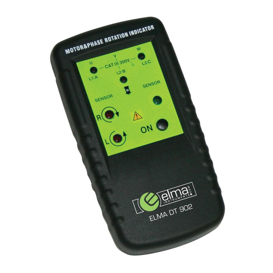
Elma DT902 side 2 Funktioner for motoromdrejningsindikator Elma DT902 Indikatorer, knapper og stik er vist på figuren herunder: 1. Testlednings stik Test lead input jack MOTO R&PHASE ROTATION INDICATOR 2. L1, L2, L3 indikatorer L1,L2,L3 Indicators 3. Indikator for omdrejninger i urets retning Clockwise Rotation LCD Indicator 4. -
Page 6: Ikke Kontakt" Omdrejningsindikering
Elma DT902 side 3 ”Ikke kontakt” omdrejningsindikering For bestemmelse af omdrejninger uden kontakt: • Frakobl alle testledninger fra motoromdrejningsindikatoren. • Påsæt indikatoren på motoren så den er parallel med længden af motorhuset. Indikatoren skal minimum være 1 tomme eller tættere på motoren. Se figur 3. -
Page 7: Bestemmelse Af Motorforbindelsen
Elma DT902 side 4 Bestemmelse af motorforbindelsen • Forbind den ene ende af testledningerne til motoromdrejningsindikatoren. Vær sikker på at L1, L2 og L3 testledningerne er forbundet til det pågældende stik. • Forbind krokodillenæbbene til den anden ende af testledningerne. -
Page 8: Sikkerhedsinformationer
C a u tio n id e n tif ie s c o n d itio n s a n d skade Elma DT902. a c tio n s th a t m a y d a m a g e th e D T - 9 0 2... -
Page 9: Tekniske Specifikationer
Elma DT902 side 6 Tekniske specifikationer Generelt Miljømæssige funktionstemperaturer: 0°C til + 40°C Max arbejdshøjde: 2000 meter Forureningsgrad: Kapslingsklasse: IP40 Mekaniske specifikationer Mål (HxBxD): 130mm x 69mm x 32mm Vægt: 130 gram Fugtighed: 15% til 80% Sikkerhedsspecifikationer Elektriske sikkerhedsstandarder: DIN VDE 0411, IEC 61010 DIN, VDE 0413-7, IEC 61557-7/EN 61557-7 Maksimal funktionsspænding:... -
Page 10: Introduction
Elma DT902 side 7 ELMA DT902 MOTOR&PHASE ROTATION INDICATOR Introduction The Motor and Phase Rotation indicator is a handheld, battery-operated instrument designed to detect the rotary field of three-phase systems and determine motor-rotation direction. Symbols The following symbols appear on the Motor and Phase Rotation indicator or in this manual. -
Page 11: Elements Of The Motor And Phase Rotation Indicator
Elma DT902 side 8 Elements of the Motor and Phase Rotation indicator Indicators, buttons, and jacks are shown in Figure 1. Test lead input jack MOTOR&PHASE ROTATION INDICATOR L1,L2,L3 Indicators Clockwise Rotation LCD Indicator Counter-Clockwise Rotation LCD Indicator ON/OFF button... -
Page 12: Non-Contact Rotary Field Indication
Elma DT902 side 9 Non-contact Rotary Field Indication For non-contact rotary field indication: • Disconnect all test leads from the Motor and Phase Rotation indicator. • Position the Indicator on the motor so that it is parallel to the length of the motor shaft. -
Page 13: Determine The Motor Connection
Elma DT902 side 10 Determine the Motor Connection • Connect one end of the test leads to the Motor and Phase Rotation indicator. Make sure the L1, L2, and L3 test leads are connected to the corresponding jack. • Connect the alligator clamps to the other end of the test leads. -
Page 14: Unpacking The Motor And Phase Rotation Indicator
Elma DT902 side 11 Unpacking the Motor and Phase Rotation indicator The Motor and Phase Rotation indicator ships with the following items: 3 test leads 3 test probes 3 alligator clips 9 V battery Users Manual Safety Information C a u tio n id e n tif ie s c o n d itio n s a n d... -
Page 15: Specifications
Elma DT902 side 12 Specifications Generel specifications Environmental Operating Temperature: 0℃ to +40℃ Operating Altitude: 2000 m Pollution Degree: Type of protection: IP 40 Mechanical Specifications Size (H x W x D): 130mm x 69mm x 32mm. Weight: 130g Humidity:... -
Page 16: Introduktion
Elma DT902 side 13 MOTOR&PHASE ROTATION INDICATOR Introduktion Rotationsriktningsvisaren är ett handhållet, batteridrivet instrument designat för att påvisa rotationsfältet på ett 3-fassystem och därmed bestämma motorns rotationsriktning. Symboler Följande symboler dyker upp antingen i denna manual eller på instrumentet: Tabell 1: Symboler Risk för elektrisk stöt... -
Page 17: Funktioner För Rotationsriktningsvisare Elma Dt902
Användning av Elma DT902 Bestämning av rotationsriktningen För att bestämma rotationsriktningen görs följande: • Förbind den ena änden av testledningarna till Elma DT902. Se till att L1, L2 och L3 är anslutna till rätt plats. • Förbind testprobarna till andra änden av testledningarna. -
Page 18: Icke Kontakt" Rotationsindikering
Elma DT902 side 15 ”Icke kontakt” rotationsindikering För att bestämma rotation utan kontakt: • Frånkoppla alla testledningar från instrumentet. • Lägg instrumentet på motorn så det ligger längs med motoraxeln. Det får max vara 1 tums avstånd till motorn. Se figur 3. -
Page 19: Bestämning Av Plintkoppling (På Motorn)
Elma DT902 side 16 Bestämning av plintkoppling (på motorn) • Förbind den ena änden av testledningarna till instrumentet. Säkerställ att L1, L2 och L3 är förbundna till rätt anslutning. • Förbind krokodilklämmorna till den andra änden av testledningarna. • Förbind krokodilklämmorna till motorplinten, L1 till U, L2 till , L3 till W. -
Page 20: Säkerhetsinformation
Elma DT902 side 17 Säkerhetsinformation Varning! Kan skada instrumentet. C a u tio n id e n tif ie s c o n d itio n s a n d a c tio n s th a t m a y d a m a g e th e D T - 9 0 2 Varning! Kan skada användaren. -
Page 21: Tekniska Specifikationer
Elma DT902 side 18 Tekniska specifikationer Generellt Användningstemperatur: 0°C til + 40°C Max arbejdshöjd: 2000 meter Föroreningsgrad: Kapslingsklass: IP40 Mekaniska specifikationer Mått (HxBxD): 130mm x 69mm x 32mm Vikt: 130 gram Luftfuktighet: 15% til 80% Säkerhetsspecifikationer Elektriska säkerhetsstandarder: DIN VDE 0411, IEC 61010 DIN, VDE 0413-7, IEC 61557-7/EN 61557-7 Max arbetsspänning:... - Page 22 Elma DT902 side 19...
Need help?
Do you have a question about the DT902 and is the answer not in the manual?
Questions and answers