
Related Manuals for Xtralis Xtralis ICAM ILS-1


Summary of Contents for Xtralis Xtralis ICAM ILS-1
- Page 1 Xtralis ICAM ILS-1 Product Guide January 2009 Document Number: 16277_00 Part Number: 09-0113-10...
- Page 3 Xtralis or its representatives. Total Liability To the fullest extent permitted by law that any limitation or exclusion cannot apply, the total liability of Xtralis in relation to the products is limited to: in the case of services, the cost of having the services supplied again;...
- Page 4 Xtralis ICAM ILS-1 Product Guide Xtralis ICAM Document Conventions The following typographic conventions are used in this document: Convention Description Bold Used to denote: emphasis Used for names of menus, menu options, toolbar buttons Italics Used to denote: references to other parts of this document or other documents.
-
Page 5: Table Of Contents
Xtralis ICAM Xtralis ICAM ILS-1 Product Guide Table of Contents Introduction..........................1 Mounting the Detector ......................2 Wiring Connections........................3 Field Connections ......................3 Pipe Installation .........................5 Pipe Specification ......................5 Fixings ..........................5 Bends..........................5 End Cap..........................6 Holes..........................6 Exhaust..........................6 Filters ..........................6 Standard Pipe Configurations....................6 Detectors ............................8 Setup............................9... -
Page 7: Introduction
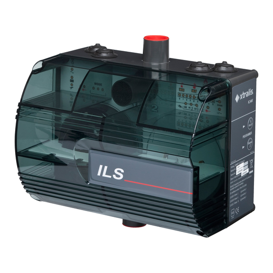
Xtralis ICAM ILS-1 Product Guide 1 Introduction The Xtralis ICAM ILS-1 system is an aspirating smoke system that utilizes an air-sampling pipe network to draw air towards one or two high-sensitivity laser point detectors in an aspirated enclosure. The use of the pipe network allows a larger area of coverage in comparison to traditional point detectors. -
Page 8: Mounting The Detector
Xtralis ICAM ILS-1 Product Guide Xtralis ICAM 2 Mounting the Detector Note: This equipment must be installed by a qualified installer in accordance with all local and national regulations. Remove the transparent cover using the special tool provided to unscrew the tamper proof fasteners. -
Page 9: Wiring Connections
Xtralis ICAM Xtralis ICAM ILS-1 Product Guide 3 Wiring Connections For correct operation of the unit it is essential that the case is fully sealed so that air can only be drawn into the system through the aspirating pipe. For this reason, all wiring must pass through the cable seals provided and no additional holes should be made. - Page 10 Xtralis VSC, a comprehensive configuration software tool available as a download from www.xtralis.com. The connector is protected with a screw-fit cover and care should be taken to ensure that the cover is securely fastened when the connector is not in use to prevent the ingress of dirt or moisture.
-
Page 11: Pipe Installation
Xtralis ICAM ILS-1 Product Guide 4 Pipe Installation A simple guide to pipe installation follows with examples of standard configurations. Note: Xtralis ASPIRE2 may be downloaded from www.xtralis.com and should be used to calculate transport times, dilution effects etc. for all installations beyond the scope of this guide. -
Page 12: End Cap
Note: Stated limits are based on EN54-20 certification testing. Reductions in pipe length may allow the fan speed to be reduced and/or number of holes or alarm threshold level increased. Results of such changes, or non-standard or unbalanced configurations, should be verified by using Xtralis ASPIRE2, Pipe Design Program. - Page 13 Xtralis ICAM Xtralis ICAM ILS-1 Product Guide 4.8.1 Single Pipe Configuration Figure 4-4: Single pipe configuration for an ILS-1 system The single pipe configuration can have a maximum length of 100 m with up to 18 x 3 mm sampling holes and a 6 mm end hole.
-
Page 14: Detectors
Xtralis ICAM ILS-1 Product Guide Xtralis ICAM 5 Detectors The ILS-1 is supplied with a single laser point detector as standard with the option for a second detector (order code: LPDET) for Redundant or Double-Knock operating modes. The detectors interface directly with the ILS-1 system. This allows the detectors status and analog smoke level output to be read and interpreted by the ILS-1 processor. -
Page 15: Setup
Xtralis ICAM Xtralis ICAM ILS-1 Product Guide 6 Setup 6.1 Display Functions ALERT Alarm ACTION Alarm BARGRAPH of Smoke level or Airflow speed FIRE Alarm SMOKE DETECTOR FAULT (1 per detector) AIRFLOW OK - HIGH AIRFLOW - LOW AIRFLOW ISOLATE... -
Page 16: User Functions
Xtralis ICAM ILS-1 Product Guide Xtralis ICAM 6.2 User Functions Figure 6-1: Programming buttons on the unit Press and hold SELECT and CHANGE keys simultaneously until the sounder beeps to initialize function selection. Press and release SELECT key to sequentially step through functions. - Page 17 Xtralis ICAM Xtralis ICAM ILS-1 Product Guide A description of ILS-1 functions are shown in the following table. Table 6-1: User Functions for the ILS-1 System Function Display Special Instructions Reset the unit To reset the unit, press CHANGE when the LED is flashing.
-
Page 18: Setup Notes
Xtralis ICAM ILS-1 Product Guide Xtralis ICAM Function Display Special Instructions Calibrate flow sensors FAN FAULT LED flashes. CHANGE key must be pressed for at least 2 seconds to initiate the flow calibration process. FAN and POWER LEDs flash to indicate calibration in progress. - Page 19 Xtralis ICAM Xtralis ICAM ILS-1 Product Guide 6.3.2 Flow Delays When airflow limits are exceeded, a Flow Fault will appear after a programmable Flow Delay time. The default Flow Delay time is approximately 30 seconds. Once the airflow is returned to a normal level, the fault condition will be cleared within 18 seconds.
-
Page 20: Testing
Xtralis ICAM ILS-1 Product Guide Xtralis ICAM 7 Testing Note: Testing should only be carried out by qualified personnel. Before undertaking any testing, ensure that the proper authorities have been informed and that the unit has been isolated from the fire control panel if necessary to prevent unwanted alarms. -
Page 21: Maintenance
Xtralis ICAM Xtralis ICAM ILS-1 Product Guide 8 Maintenance With normal use, the filter element will eventually become contaminated with dust particles. It is recommended that the filter element (order code: FL53) is replaced and detectors cleaned every six months (more frequently for dirty environments). -
Page 22: En54-20 Sensitivity Classes
• Class C: 17 x 3 mm holes plus 1 x 6 mm hole in end cap Note: Any changes to the standard configuration or settings shown above should be verified using Xtralis ASPIRE2 pipe modeling software. The latest version of ASPIRE2 is available from www.xtralis.com. -
Page 23: Problem Solving
Xtralis ICAM Xtralis ICAM ILS-1 Product Guide 10 Problem Solving Problem Possible Solutions Power light flashing Ensure supply to BATTERY connector within limits. No lights on display. Fan not Ensure supply leads correctly orientated. running Ensure that BAT FUSE correctly seated in socket and fuse not blown. -
Page 24: Specifications
Xtralis ICAM ILS-1 Product Guide Xtralis ICAM 11 Specifications Table 11-1: General ILS-1 Specifications Number of Detectors 1 or 2, Laser based Analog Addressable Filtration Single stage dust particle filter Flow Monitoring Thermal device, high and low thresholds. 10 element bar graph indication.
Need help?
Do you have a question about the Xtralis ICAM ILS-1 and is the answer not in the manual?
Questions and answers