Xtralis VESDA VLP Product Manual
Hide thumbs
Also See for VESDA VLP:
- Installation instructions (2 pages) ,
- Quick start manual (2 pages) ,
- Installation sheet (2 pages)

Related Manuals for Xtralis VESDA VLP


Summary of Contents for Xtralis VESDA VLP
- Page 1 Xtralis VESDA VLP Product Guide August 2008 Document Number: 10278_07 Part Number: 19145...
- Page 3 Xtralis or its representatives. Total Liability To the fullest extent permitted by law that any limitation or exclusion cannot apply, the total liability of Xtralis in relation to the products is limited to: (i) in the case of services, the cost of having the services supplied again;...
- Page 4 Xtralis VESDA Xtralis VESDA VLP Product Guide ® Document Conventions The following typographic conventions are used in this document. Convention Description Bold Used to denote: emphasis Used for names of menus, menu options, toolbar buttons Italics Used to denote: references to other parts of this document or other documents.
- Page 5 Xtralis VESDA ® Xtralis VESDA VLP Product Guide Codes and Standards Information for Air Sampling Smoke Detection We strongly recommend that this document is read in conjunction with the appropriate local codes and standards for smoke detection and electrical connections. This document contains generic product information and some sections may not comply with all local codes and standards.
- Page 6 • ActivFire • AFNOR • VNIIPO • CE - EMC and CPD • EN 54-20 Regional approvals listings and regulatory compliance vary between Xtralis VESDA product models. Refer to www.xtralis.com for the latest product approvals matrix. Document: 10278_06 Part: 19145 www.xtralis.com...
-
Page 7: Table Of Contents
Xtralis VESDA ® Xtralis VESDA VLP Product Guide Contents 1. Scope ............................3 2. Introduction to the VLP .......................3 VLP Features ..........................3 3. Operation of the VLP ........................3 VLP Configurations .........................5 Display module ........................6 Xtralis VESDA LCD Programmer ..................8 VLP Components ........................9 4. - Page 8 Xtralis VESDA Xtralis VESDA VLP Product Guide ® www.xtralis.com...
-
Page 9: Scope
® Xtralis VESDA VLP Product Guide 1 Scope The Xtralis VESDA VLP Product Guide is written to provide you with comprehensive knowledge of the detector. This guide introduces you to the VLP features, technical specifications and gives an understanding of its components and their function. You will also find instructions on installing, cabling and powering up the detector. - Page 10 Xtralis VESDA Xtralis VESDA VLP Product Guide ® Any smoke detected in the laser detection chamber is signaled to the main processor card. If the presence of detected smoke is higher than the set thresholds it is reported as an alert, action, fire 1 or fire 2 alarm depending upon the alarm thresholds.
-
Page 11: Vlp Configurations
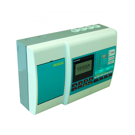
Xtralis VESDA ® Xtralis VESDA VLP Product Guide VLP Configurations The modular options available with a VLP are: • Fire and OK LEDs (FOK) • LCD Programmer • VLP Display Module Figure 2 - VLP-012 installed with LCD Programmer and Display Module... -
Page 12: Display Module
Xtralis VESDA Xtralis VESDA VLP Product Guide ® Display module The VLP Display Module is mounted either on the detector front cover or at a remote location in a remote mounting box or a 19” subrack. It provides a visual representation of the smoke levels and the four alarm stages for the assigned detector. - Page 13 Xtralis VESDA ® Xtralis VESDA VLP Product Guide The OK LED stays illuminated during normal operation indicating the unit is OK LED functioning normally. When this LED is off a warning beep sounds, indicating a Fault condition is active. This LED is illuminated when the detector is Isolated and relays are de- Isolate LED activated disabling alarm outputs of the detector.
-
Page 14: Xtralis Vesda Lcd Programmer
A hand-held model is also available. The hand-held model is connected to the VESDAnet socket on the termination card of the detector. For a detailed description and use of the LCD Programmer please refer to the Xtralis VESDA LCD Programmer Product Guide. -
Page 15: Vlp Components
Xtralis VESDA ® Xtralis VESDA VLP Product Guide VLP Components Legend Front cover Pipe inlet manifold Termination card Air filter Blank card protecting processor card Aspirator Chassis with laser detector chamber Mounting box/enclosure Figure 6 - An exploded view of the detector... -
Page 16: Vlp Product Information
Xtralis VESDA Xtralis VESDA VLP Product Guide ® 4 VLP Product Information Product Specifications Supply Voltage 18 to 30 VDC Power Consumption @24 VDC • VLP with Blank Plates Normal: 5.8 W 3,000rpm Alarm On: 7.0 W • VLP with Blank Plates @ Normal: 9.6 W... - Page 17 Xtralis VESDA ® Xtralis VESDA VLP Product Guide Threshold Setting Range Alert: 0.005 - 1.990% obs/m (0.0015 - 0.6218% obs/ft.) Action: 0.010 - 1.995% obs/m (0.0031 - 0.6234% obs/ft.) Fire 1: 0.015 - 2% obs/m (0.0046 - 0.625% obs/ft.) Fire 2: 0.020 - 20% obs/m...
-
Page 18: Vlp Dimensions
Xtralis VESDA Xtralis VESDA VLP Product Guide ® VLP Dimensions Figure 7 - VLP dimensions - rear view www.xtralis.com... - Page 19 Xtralis VESDA ® Xtralis VESDA VLP Product Guide Figure 8 - VLP dimensions www.xtralis.com...
-
Page 20: Default Settings
Xtralis VESDA Xtralis VESDA VLP Product Guide ® Default Settings Range Access Parameter Default Value Level Minimum Maximum Event Log - Events • Smoke Level Enabled • Alarms Enabled • Faults Enabled • User Action Enabled Fire 2 Threshold 2% obs/m 0.625% 0.02% obs/m... -
Page 21: Relays
Xtralis VESDA ® Xtralis VESDA VLP Product Guide Range Access Parameter Default Value Level Minimum Maximum Reference detector: • Reference Zone No. Selectable Selectable • Dilution 100% 100% • Delay 2 minutes 0 minutes 15 minutes Display - relay Card... -
Page 22: Relays Default Settings
Xtralis VESDA Xtralis VESDA VLP Product Guide ® Note: Assignments to relays 3 and 6 are fixed to Urgent Fault and Fire 1 respectively. These relays may be assigned additional assignments. Relay # Default State change Latch Isolate Energizes when an operator isolates the detector by... -
Page 23: General Purpose Input (Gpi) Functions
Xtralis VESDA ® Xtralis VESDA VLP Product Guide General Purpose Input (GPI) Functions The input terminal requires a voltage supply between 5V and 30 VDC to operate. The input is isolated from the system by an opto-coupler device. Connect the GPI + terminal to the positive output and the GPI - terminal to the ground output of the external device. - Page 24 Xtralis VESDA Xtralis VESDA VLP Product Guide ® Note: When the night-time threshold is configured as a GPI function, it overrides the clock settings for day-start and night-start. When using the standby or remote isolate options it is recommended that all displays on VESDAnet are configured to have the Isolate button disabled.
-
Page 25: Mounting The Vlp
Xtralis VESDA ® Xtralis VESDA VLP Product Guide 5 Mounting the VLP The VLP detector can be mounted onto the wall or on any suitable secure surface using the mounting bracket. It is strongly recommended that the detector is mounted on to the mounting bracket included with the packaging. -
Page 26: Mounting The Vlp In The Inverted Orientation
Xtralis VESDA Xtralis VESDA VLP Product Guide ® Mounting the VLP in the Inverted Orientation If the detector is fitted with a LCD Programmer and/or a Display Module, re-orient these to the upright position. Mount the detector in inverted orientation onto the mounting bracket. -
Page 27: Recess Mounting Kit
Xtralis VESDA ® Xtralis VESDA VLP Product Guide Recess mounting kit These kits are used to house a detector inside a wall cavity. Figure 12 - Recess mounting kit www.xtralis.com... -
Page 28: Connecting The Vlp To The Pipe Network
Xtralis VESDA Xtralis VESDA VLP Product Guide ® 6 Connecting the VLP to the Pipe Network Inlet Pipes The inlets in the pipe inlet manifold are designed to receive a standard pipe of 25 mm (1 in) OD. A 25 mm to 1.050 inches adaptor to fit the pipe inlet manifold is included for all shipments to USA. -
Page 29: Managing The Exhaust Air
Xtralis VESDA ® Xtralis VESDA VLP Product Guide Managing the Exhaust Air To exhaust air from the detector, use the exhaust ports at the rear or at the bottom of the head mounting box. Remove the appropriate exhaust port plugs and if required, connect an outlet pipe to the exhaust manifold. -
Page 30: Vlp Wiring Connections
VESDAnet cables are terminated at the VESDAnet A and B Terminals on the termination card. Communication wires from another Xtralis VESDA device are brought into the detector at one terminal and looped out to another device on VESDAnet from the other terminal. -
Page 31: Connections For Gpi
Xtralis VESDA ® Xtralis VESDA VLP Product Guide The VLP detector is shipped with the VESDAnet A and B terminals looped. If the detector is not to be networked with other devices, then do not disturb this loop. Remove this loop to connect the detector to the VESDAnet. -
Page 32: Typical Wiring To Fire Alarm Control Panel (Facp)
Figure 19 - Typical wiring to a fire panel with EOL Wiring To an Address Loop Module. This wiring example is for wiring Xtralis VESDA detectors to a typical Address Loop module 3 input 1 output. These are example drawings. Refer to the appropriate product manual for the exact wiring details of the third party equipment. -
Page 33: Power Source
Xtralis VESDA ® Xtralis VESDA VLP Product Guide 8 Power Source There are two sets of power terminals on the termination card. Use one set to connect to a 24 VDC power supply and if required loop out to another device via the second set. The detector has reverse polarity protection to minimize the risk of reverse power connection to the detector. -
Page 34: Back Up Battery
Xtralis VESDA Xtralis VESDA VLP Product Guide ® 9 Back Up Battery The power supply for the VLP detector is switched to a back up battery in the event of a mains power supply disruption. The size of the back up battery is determined by local standards and codes, the total power required by the system, back up time required, allowance for reduction in capacity with age and expected temperature variations. -
Page 35: Powering Up
3000 rpm to conserve power. 10 Powering Up A VLP detector must be powered up by Xtralis VESDA accredited personnel only. After installing the VLP detector it is necessary to power up the system. The system takes approximately 15 seconds to power up. -
Page 36: Installation Checklist
Xtralis VESDA Xtralis VESDA VLP Product Guide ® Installation Checklist Site Name Address Detector Serial Number(s) and Date of Manufacture Interface Card Serial Number & Date of Manufacture Name of Installer Signature Date Perform the following checks listed below to ensure that all the necessary items are completed before handing over to a commissioning engineer. -
Page 37: Preliminary Systems Check
Xtralis VESDA ® Xtralis VESDA VLP Product Guide 11 Preliminary Systems Check A preliminary systems check is required after installing the VLP detector, before it is commissioned for use. The check can be conducted by connecting the detector to a LCD Programmer or using VSC or VSM4 PC based software. -
Page 38: Replacing The Chassis/Air Inlet Pipe Manifold
Xtralis VESDA Xtralis VESDA VLP Product Guide ® Replacing the chassis/Air Inlet Pipe Manifold Isolate unit by pressing the Isolate button on the zone configured display or by selecting Isolate Zone from the Zone menu in VSC or VSM4. This isolates the outputs from the unit to a Fire Alarm Control Panel. - Page 39 Xtralis VESDA ® Xtralis VESDA VLP Product Guide Figure 24 - Remove the chassis Caution: Care must be taken not to damage the cable running to the manifold. Note: The chassis consists of the Detection Chamber, head processor card and flow sensors.
-
Page 40: Internal Wiring For Vlp
Xtralis VESDA Xtralis VESDA VLP Product Guide ® Internal Wiring for VLP The table below provides the cable loom interconnecting details inside the detector. Use the look up table in conjunction with the attached circuit diagram to assist with maintenance. - Page 41 Xtralis VESDA ® Xtralis VESDA VLP Product Guide Legend Detector chamber Programmer module Display module Detector terminal card Processor card Aspirator Flow sensor card Figure 26 - Internal wiring diagram www.xtralis.com...
-
Page 42: Spare Parts
Xtralis VESDA Xtralis VESDA VLP Product Guide ® Spare Parts On larger sites having multiple detectors it is advisable to stock certain critical spare parts. A suggested list of spare parts with quantities is given below: Number of detectors Installed to warrant ONE spare part Part No. - Page 43 Xtralis VESDA ® Xtralis VESDA VLP Product Guide Index ........31 Check Pipe Flow ......31 Check Pipe Network ......31 Clean Sampling Point ..........7 Action ......... 15 Communications ........16 Action relay ... 22 Connecting VLP to Pipe Network .........
- Page 44 Xtralis VESDA ® Xtralis VESDA VLP Product Guide .......... 3 Features list ..........7 Filter fault ........31 Filter Inspection ......4 Laser detection chamber ......14 Filter Service Interval ........5 LCD Programmer ........... 7 Fire 1 ........8 LCD programmer ..........
- Page 45 Xtralis VESDA ® Xtralis VESDA VLP Product Guide ........29 ......7 Powering up Threshold Indicators ........15 ........ 11 Preferred Port Threshold Setting ....31 Preliminary Systems Check .......... 8 Programmer ........8 Push Button Keys .......... 15 UL Version ........
- Page 46 Xtralis VESDA ® Xtralis VESDA VLP Product Guide www.xtralis.com...
Need help?
Do you have a question about the VESDA VLP and is the answer not in the manual?
Questions and answers