Table of Contents
Advertisement
Quick Links
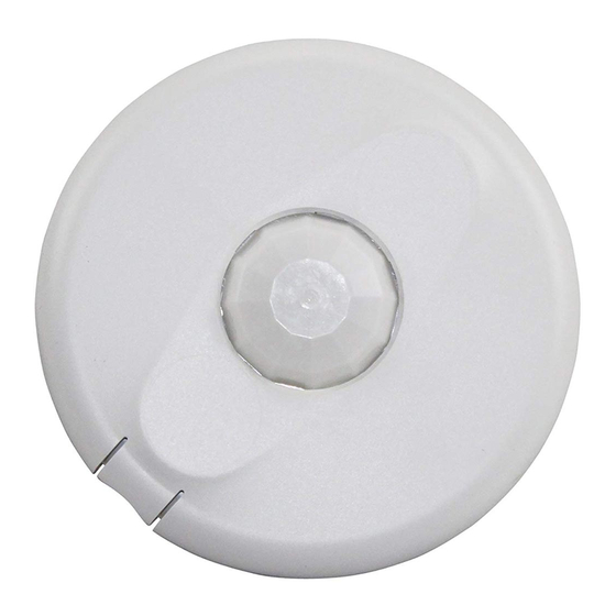
360° Passive Infrared • Low Voltage
Specifications
Voltage ..........................18-28VDC/VAC, half wave rectified AC
Current Consumption ..................................................... 10 mA
Power Supply ..................................WattStopper Power Packs
Operating Temperature ..................... 32° to 131°F (0° to 55°C)
Time Delay Adjustment ....................30 seconds to 30 minutes
Walk-Through Mode ...3 minutes if no activity after 30 sec.
Test Mode ............................... 5 sec. upon DIP switch reset
PIR Coverage
Model CI-305 .................................................... up to 1200ft
Model CI-305-1 .................................................. up to 500ft
Sensitivity Adjustment ................. High or Low (DIP switch)
UL & CUL Listed for use with WattStopper Power Packs
CI-305
Occupancy Sensor
with Manual On feature
Santa Clara, CA 95050
v3
2
2
Advertisement
Table of Contents

Related Manuals for wattstopper CI-305


Summary of Contents for wattstopper CI-305
- Page 1 Test Mode ....... 5 sec. upon DIP switch reset PIR Coverage Model CI-305 ............ up to 1200ft Model CI-305-1 ..........up to 500ft Sensitivity Adjustment ....High or Low (DIP switch) UL & CUL Listed for use with WattStopper Power Packs Santa Clara, CA 95050...
-
Page 2: Unit Description
COVERAGE PATTERN The CI-305 sensors provide a 360° coverage pattern. Two lens patterns are available. The CI-305 provides up to 1200 square feet of coverage and the CI-305-1 provides up to 500 square feet of coverage. The coverage shown represents walking motion at a mounting height of 8 feet. -
Page 3: Placement Guidelines
4 to 6 feet away from air supply ducts as rapid air currents or the differences in temperatures may cause false activations. Mount the sensor to the ceiling. The CI-305 sensors are designed for a ceiling height of about 8-10 feet. Mounting above or below this range will significantly affect the coverage patterns. - Page 4 Turn power off at the circuit breaker before installing power packs or sensors. Each WattStopper BZ series power pack can supply power for 14 CI-305 sensors. When using more sensors than this, multiple power packs are required. Refer to the wiring diagram on the next...
-
Page 5: Connecting Wires
Low Voltage Load #2 Class 2 (Optional) Line Black Voltage Common Blue Control Out +24V Ceiling Depluggable Terminal Spring Clips (2) Rear Housing Line Voltage Switches Front Cover CI-305 Standard wiring with local off switch Visit our website for FAQs: www.wattstopper.com... - Page 6 Class 2 +24V Blue +24V Black Man.Switch Control Out Jumper Common Back Man.Switch LVS-1 Ceiling Depluggable Terminal Spring Clips (2) LVS-1 Rear Housing For low voltage momentary switch set DIP switch #7 ON Front Cover CI-305 Call 800.879.8585 for Technical Support...
-
Page 7: Mounting The Sensor
5. Push the sensor up into the J -Box and twist it so that the mounting screws are seated in the keyhole slots. 6. Tighten the two screws to secure the sensor to the J-Box. 7. Snap the front cover onto the sensor. Visit our website for FAQs: www.wattstopper.com... -
Page 8: Sensor Adjustment
SENSOR ADJUSTMENT This unit is pre-set for basic operation as described in this guide. Adjustment is optional. The sensors are factory preset to allow for quick installation in most applications. Verification of proper wiring or coverage, or customizing the sensor’s settings can be done using the following procedures. -
Page 9: Dip Switch Setting
DIP Switch Setting Chart DIP SWITCH SETTING The CI-305 has 7 DIP switches under the cover. Switch# 1 2 3 Time Delay Time Delay: Switches 1, 2, 3 Test Mode/20 min The sensor will hold the lights ON as long as 30 seconds occupancy is detected. -
Page 10: Overload Protection
Manual On: In this mode, the switch is required to turn on the load. The sensor is then used to keep the load on, based on occupant activity. After the time delay ends, if there is no movement detected within the 30 second re-trigger period the manual switch must be used to turn ON the load. -
Page 11: Troubleshooting
• Turn sensitivity and time delay to minimum and allow the sensor to time out. • If the lights turn off, the sensor is working properly (see number 1, above, and “Sensor Adjustment” for readjustment of sensor). Visit our website for FAQs: www.wattstopper.com... -
Page 12: Ordering Information
Auxiliary Relay Pack: 120/277VAC, 60Hz, 20A Ballast 347VAC, 60Hz, 15A Ballast All sensors are white. BZ series power packs supply power for up to 14 CI-305 sensors. WARRANTY INFORMATION WattStopper warranties its products to be free of defects in materials and workmanship for a period of five (5) years.
Need help?
Do you have a question about the CI-305 and is the answer not in the manual?
Questions and answers