Table of Contents
Advertisement
Specifications
Voltage 18-28VDC/VAC, half wave rectified AC
Current Consumption
Model UT-305-1, Model UT-305-2 .............................. 30mA
Model UT-305-3 .......................................................... 35mA
Power Supply .................................Watt Stopper Power Packs
Operating Temperature ..................... 32° to 131°F (0° to 55°C)
Time Delay Adjustment .................................... 5 to 30 minutes
Walk-Through Mode ...3 minutes if no activity after 30 sec.
Test Mode .5 sec. upon intial power-up or DIP switch reset
Ultrasonic Coverage
Model UT-305-1 ................................................ up to 500 ft
Model UT-305-2 .............................................. up to 1000 ft
Model UT-305-3 .............................................. up to 2000 ft
Sensitivity Adjustment ..... Minimum to Maximum (trimpot)
Frequency .................................................................. 40kHz
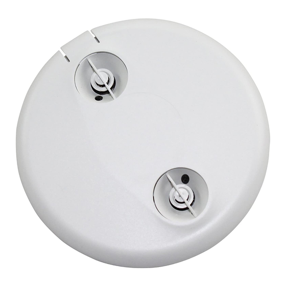
UT-305
Ultrasonic • Low Voltage
Occupancy Sensor
2
2
2
Advertisement
Table of Contents

Related Manuals for wattstopper UT-305


Summary of Contents for wattstopper UT-305
-
Page 1: Specifications
Walk-Through Mode ...3 minutes if no activity after 30 sec. Test Mode .5 sec. upon intial power-up or DIP switch reset Ultrasonic Coverage Model UT-305-1 ..........up to 500 ft Model UT-305-2 ..........up to 1000 ft Model UT-305-3 ..........up to 2000 ft Sensitivity Adjustment .. -
Page 2: Unit Description
SmartSet automatically adjusts the time delay to usage patterns in the controlled space. The UT-305 can be configured to turn lighting on, and hold it on as long as it detects cccupancy. After no movement is detected for a user specified or SmartSet time (5 to 30 minutes) the lights are switched off. -
Page 3: Placement Guidelines
4 to 6 feet away from air supply ducts. Mount the sensor to the ceiling. The UT-305 is designed for a ceiling height of about 8-10 feet. Mounting above or below this range will significantly affect the coverage patterns. -
Page 4: Wiring Directions
WIRING DIRECTIONS CAUTION TURN POWER OFF AT THE CIRCUIT BREAKER BEFORE INSTALLING POWER PACKS OR SENSORS. Each WattStopper BZ series power pack can supply power for 4 UT-305 sensors. When using more sensors than this, multiple power packs are required. 03624r2... - Page 5 Neutral Load #1 Power Pack Low Voltage Load #2 Class 2 (Optional) Line Black Voltage Common Blue Control Out +24V Ceiling Depluggable Terminal Spring Clips (2) Rear Housing Line Voltage Switches Front Cover UT-305 Visit our website for FAQs: www.wattstopper.com...
-
Page 6: Line Voltage
Class 2 Blue +24V Control Out Black Common Man.Switch Common Jumper Man.Switch Back LVS-1 Ceiling Depluggable Terminal Spring Clips (2) LVS-1 Rear Housing For low voltage momentary switch, set Front Cover DIP switch #1 ON UT-305 Call 800.879.8585 for Technical Support... -
Page 7: Mounting The Sensor
5. Push the sensor up into the J -Box and twist it so that the mounting screws are seated in the keyhole slots. 6. Tighten the two screws to secure the sensor to the J-Box. 7. Snap the front cover onto the sensor. Visit our website for FAQs: www.wattstopper.com... -
Page 8: Sensor Adjustment
SENSOR ADJUSTMENT The sensors are factory preset to allow for quick installation in most applications. Verification of proper wiring or coverage, or customizing the sensor’s settings can be done using the following procedures. To make adjustments, open the Front Cover with a small screwdriver. -
Page 9: Dip Switch Setting
Logic Configuration Chart DIP SWITCH SETTING The UT-305 has 6 DIP switches. They are used On Mode to set manual/automatic on/off functions, time delay and sensor activation LED settings. Auto On Manual On On Mode: Switch 1 The Manual ON function is facilitated by Override... -
Page 10: Override: Switch
ON and the sensor reverts to the automatic-on mode. • Once the sensor returns to automatic-on mode, either the switch or occupancy detection can turn the load ON. Override: Switch 2 To override all sensor functions, set DIP switch 2 to the ON position. The green LED comes on and stays on for the duration of the override. This bypasses the occupancy detection control functions of the sensor, but still allows the lights to be manually controlled with a light switch, if one is installed. -
Page 11: Troubleshooting
4. Set sensitivity and time delay to minimum and allow the sensor to time out. If the lights turn off, the sensor is working properly (see number 1, above, and “Sensor Adjustment” for readjustment of sensor). Visit our website for FAQs: www.wattstopper.com... -
Page 12: Ordering Information
Power Pack: 120/277VAC, 50/60Hz, 225mA, 20A ballast or incandescent, 1HP@120/250VAC S120/277/347E-P Auxiliary Relay Pack: 120/277VAC, 60Hz, 20A Ballast 347VAC, 60Hz, 15A Ballast All sensors are white. BZ series power packs supply power for up to 4 UT-305 sensors. Call 800.879.8585 for Technical Support... -
Page 13: Warranty Information
There are no obligations or liabilities on the part of WattStopper for consequential damages arising out of or in connection with the use or performance of this product or other indirect damages with respect to loss of property, revenue, or profit, or cost of removal, installation or reinstallation.
Need help?
Do you have a question about the UT-305 and is the answer not in the manual?
Questions and answers