Table of Contents
Advertisement
Quick Links
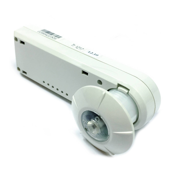
UNIT DESCRIPTION
The LMLS-400 is a closed loop photosensor that measures
the ambient light level in order to automatically switch or
dim one zone of lighting. It is part of the Digital Lighting
Management (DLM) system and sends light level signals
to control loads connected to DLM switching or dimming
room controllers. The LMLS-400 has photodiodes
with an extended range of 1-6,553 footcandles (fc), and
photopic correction to mimic the human eye, for precise
measurement of visible light.
The LMLS-400 operates on Class 2 power supplied to a DLM
local network by one or more DLM room controllers.
Plug n' Go automatic configuration assigns the photosensor
to control load 1. Loads may be reassigned using an
LMCT-100. Following a manual or automatic setup process,
the LMLS-400 monitors the ambient light in the controlled
space and works with the room controller(s) to maintain the
design light level. The LMLS-400 uses switching or dimming
setpoints and other control parameters to manage the light
levels throughout the day regardless of changing daylight
contribution.
Sensor Installation and Configuration Overview
Mount the photosensor so that the Photosensor Viewing Port
1.
views the daylight and electric light combined.
2. Complete all wiring and turn ON power to the room controller.
3. Use the LMCS-100 or LMCT-100 configuration tool to complete the
configuration process. The LMLS-400 will not operate properly until the
configuration and calibration is successful.
A. Select the LMLS-400 to be configured, from the Daylighting
menu.
Use Zone Setup to select the operating mode for the
B.
controlled zone (Switched, Bi-Level, Tri-Level, or Dimmed).
C. Assign individual loads to the LMLS-400 controlled zone.
Calibrate the LMLS-400 either automatically or manually.
D.
If manual calibration is chosen a light meter will be
required.
E. Adjust Zone Settings and Advanced Settings to meet specific
sequence of operation requirements.
F. Use Test Mode to verify the LMLS-400 operation.
LMLS-400/400-L
Digital Lighting Management
Single Zone Photosensor
SPECIFICATIONS
Light sensor range .......................................1 to 6,553 fc
Voltage ..................................................................24VDC
Current Consumption ...............max 13mA, typical 3mA
Power Supply ............................ DLM Room Controllers
Connection to the DLM Local Network ........1 RJ45 port
Environment:
Operating Temperature ..... 32° to 131°F (0° to 55°C)
Storage Temperature ...... 23° to 140°F (-5° to 60°C)
Relative Humidity ............ 5 to 95% (non condensing)
Other:
RoHS compliant, 5-year warranty
Dimensions:
LMLS-400/400-L
Length ..................................................... 3.9" (99mm)
Width ....................................................... 1.2" (30mm)
Depth .....................................Minimum 1.0" (25mm)
Tube Diameter .......................................... 0.88" (22mm)
Ceiling Tile Thickness:
LMLS-400 ........................................ 0" - 5/8" (16mm)
LMLS-400-L ................. 5/8" (16mm) - 1.25" (31mm)
FACTORY DEFAULTS
Switching Operation:
ON Setpoint* .......................................................7.5 fc
OFF Setpoint* ......................................................11 fc
ON Time Delay .................................................. 20 sec
OFF Time Delay ............................................... 10 min
Dimming Operation:
Day Setpoint* .......................................................50 fc
Night Setpoint* ....................................................10 fc
Ramp Rate Up ........................................ 20% per sec
Ramp Rate Down ...................................... 2% per sec
Cut Off Delay ......................................................Never
Advanced Parameters:
Allow Override ........................................................No
Override Time .................................................. Infinity
Hold OFF .................................................................No
Scenes Stop Daylighting ........................................No
Ignore After Hours .................................................No
* Setpoints change automatically upon calibration
Closed Loop
Maximum 1.5" (38mm)
Advertisement
Table of Contents

Related Manuals for wattstopper LMLS-400


Summary of Contents for wattstopper LMLS-400
- Page 1 Relative Humidity .... 5 to 95% (non condensing) measurement of visible light. Other: RoHS compliant, 5-year warranty The LMLS-400 operates on Class 2 power supplied to a DLM Dimensions: local network by one or more DLM room controllers. LMLS-400/400-L Plug n’ Go automatic configuration assigns the photosensor Length .............
-
Page 2: Placement Guidelines
IR COMMUNICATION Lens If the photosensor is mounted at ceiling heights greater Note: For ceiling thickness lower than 5/8”, the LMLS-400 than 20’, communication with the photosensor must must be used. be through another IR enabled DLM device such as an occupancy sensor or a wallswitch. -
Page 3: Wiring Directions
Room stop flashing and turn on solid; releasing the button Controller at this time will cause the LMLS-400 to clear its load bindings, but otherwise leave its internal parameters unmodified. • Press and hold for 20 seconds – if the button is held down for twenty seconds or more, the red LED again starts to flash;... -
Page 4: Operating Modes
When only one Increasing the light level above that set by daylighting is LMLS-400 is found, it is automatically assigned to Load 1. possible only if Allow Override is set to Yes (the default is Based on the attributes of the room controller, the LMLS- No). - Page 5 Fig. 12: LMCT-100 Controls The LMCT-100 Wireless IR Configuration Tool is a handheld tool for setup and testing of WattStopper Once active, use the Select button to move to a menu or Digital Lighting Management (DLM) devices. function within the active field.
-
Page 6: Selecting The Operation Mode
LMLS-400 CONFIGURATON PROCESS ZONE SETUP Selecting the Operation Mode B AT D a y l i g h t i n g C o n fi g S e n s o r C o n fi g u r a t i o n L o a d C o n fi... - Page 7 Z o n e S e t t i n g s Parameters menu. A d v a n c e d S e t t i n g s C o n t r o l M o d e www.wattstopper.com Page 7...
- Page 8 Bi-Level Load Assignment Tri-Level Load Assignment Z o n e S e t u p L M L S - 4 0 0 Z o n e S e t u p L M L S - 4 0 0 Z o n e S e t u p L M L S - 4 0 0 Z o n e S e t u p...
-
Page 9: Manual Calibration
: < 5 0 f c > t h e n e t w o r k 5. Remove any objects that may affect the LMLS-400 light A c t u a l L i g h t L e v e l a t P r e s s S e l e c t a t t h e w o r k p l a n e : <... - Page 10 ZONE SETTINGS To set the desired light level, point to the LMLS-400 and Zone Settings allows you to modify the photosensor continue pointing to it while pressing the keys. Daylighting Setpoints, Time Delays and Ramp Rates. key increments and the key decrements the light ...
- Page 11 A d v a n c e d S e t t i n g s C o n t r o l M o d e Cut Off Delay LMLS-400 Daylighting Menu The time that the controlled D a y l i g h t i n g...
-
Page 12: Advanced Settings
After choosing Control Mode and and then will begin to adjust based upon daylight. pressing Select, point to the LMLS-400 and press Select. The current control mode is displayed. This can be If Hold Off = <Yes>, the sensor will limit the loads to the changed to Normal, Test, Demo, or Disable. - Page 13 Disable: Test Mode shortens timeouts for switching operation, and speeds ramp rates for dimming operation, to allow Disable mode prevents the LMLS-400 from controlling quick verification. Test Mode cancels automatically after any daylighting loads. This parameter is mostly used for 5 minutes.
-
Page 14: Troubleshooting
WARRANTY INFORMATION WattStopper warranties its products to be free of defects in materials and workmanship for a period of one (1) year. There are no obligations or liabilities on the part of WattStopper for consequential damages arising out of, or in connection with, the use or performance of this product or other indirect damages with respect to loss of property, revenue or profit, or cost of removal, installation or reinstallation.
Need help?
Do you have a question about the LMLS-400 and is the answer not in the manual?
Questions and answers