Advertisement
Quick Links
THIS UNIT IS PRE-SET FOR PLUG n' GO™
OPERATION, ADJUSTMENT IS OPTIONAL.
For full operational details, adjustment and more
features of the product, see the DLM System
Installation Guide provided with the LMRC-102 and
www.wattstopper.com
also available at
INSTALLATION SHALL BE
IN ACCORDANCE WITH ALL
APPLICABLE REGULATIONS,
LOCAL AND NEC CODES.
Intended for Listed Class
2 DLM Devices.
For Class 2 DLM devices -
To be connected to a Class
2 power source only.
SENSOR PLACEMENT (10' MAX. HEIGHT)
Sensor
COVERAGE PATTERN
The LMDC-100 provides a 360° coverage pattern. The
coverage shown represents walking motion at a mounting
height of 10 feet.
CONNECTIVITY
The illustrations below show examples of free-topology wiring. The LMDC-100
communicates to all other Digital Lighting Management devices connected to the low
voltage DLM Local Network, regardless of their position on the DLM Local Network.
Corner Mount
Ceiling Mount
Sensor
Sensor
DLM Local Network
Switch
Switch
Daylight Sensor
For Class 2 Device Wiring Only –
Do Not Reclassify and Install as
Class 1, or Power and Lighting
Wiring.
Wire connections shall be rated
suitable for the wire size (lead
and building wiring) employed.
25'
25'
Line
Voltage
Low Voltage
LMRJ Cables
Line/Hot
Neutral
Black wire
White wire
LMRC
102
Room
Controller
Red wire
to Load A (1)
J-Boxes
Voltage ................................................................................ 24VDC
Current Consumption .......................................................... 20mA
Power Supply .............. Watt Stopper/Legrand Room Controllers
Connection to the DLM Local Network ...................2 RJ-45 ports
DLM Local Network Characteristics:
Provides low voltage power over Cat 5e cable (LMRJ).
Supports up to 24 communicating devices, including 4
LMRC-10x or LMPL-101 max per each DLM Local Network.
Free topology up to 1,000ft of low voltage cable.
Environment ................................................. For Indoor Use Only
Operating Temperature ....................32° to 131°F (0° to 55°C)
Storage Temperature ...................... 23° to 176°F (-5° to 80°C)
Relative Humidity ...........................5 to 95% (non condensing)
Patent Pending
PIR
Coverage
Ultrasonic
Coverage
25 ft x 25 ft
(7.62m x 7.62m)
Loads
To
Load
1
2
Yellow wire
to Load B (2)
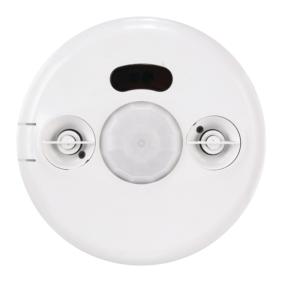
LMDC-100
Digital Lighting Management
Dual Technology Ceiling Mount
Occupancy Sensor
Pendant
Strong air
fixture
Sensor
supply
6'
Mount sensor at least 6' away from hot air supply.
Avoid obstacles that block sensor's line-of-sight.
25 ft
(7.62m)
Room
Controller
J Box
Switch
Ceiling Mount
Occupancy
Sensor
Advertisement

Related Manuals for wattstopper LMDC-100


Summary of Contents for wattstopper LMDC-100
- Page 1 25 ft x 25 ft (7.62m x 7.62m) CONNECTIVITY The illustrations below show examples of free-topology wiring. The LMDC-100 communicates to all other Digital Lighting Management devices connected to the low voltage DLM Local Network, regardless of their position on the DLM Local Network.
-
Page 2: Troubleshooting
LEDs turn ON and OFF but 1. Make sure device is not in PnL. load doesn’t switch 2. Check load connections to room controller. Please 6/2009 2800 De La Cruz Blvd. Phone: 800.879.8585 Recycle Santa Clara, CA 95050 www.wattstopper.com 11434...
Need help?
Do you have a question about the LMDC-100 and is the answer not in the manual?
Questions and answers
I have an LMDC -100 sensor in an office that keeps going off when the occupant is in a meeting. How do I either increase the amount of time that the light turns off or disable it all together.
To increase the time delay or disable the Wattstopper LMDC-100 sensor, follow these steps:
1. Increase Time Delay: The factory preset for the time delay is 20 minutes. You can adjust this by accessing the sensor's settings and modifying the time delay parameter. Refer to the specific instructions for adjusting settings in the manual or on the device.
2. Disable the Sensor: To disable the sensor, hold the load button for over 20 seconds. The blue LED will flash, indicating that the sensor has been reset or disabled.
Make sure all connections are correct and follow the appropriate safety precautions when performing these actions.
This answer is automatically generated