Table of Contents
Advertisement
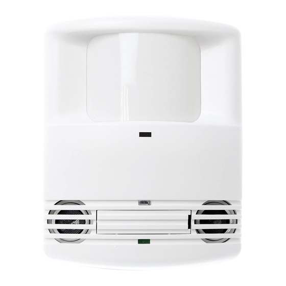
Dual Technology • Low Voltage
with Isolated Relay and Manual On features
SPECIFICATIONS
Voltage ............................................................. 18-28VDC/VAC
Current Consumption ...................................................... 43mA
Power Supply ..................................WattStopper Power Packs
Isolated Relay Rating ...................................... 1A @30VDC/VAC
Operating Temperature ..................... 32° to 131°F (0° to 55°C)
Light Level One-Step Adjustment .....................10FC to 300FC)
Time Delay Adjustment .................................... 5 to 30 minutes
Walk-Through Mode ...3 minutes if no activity after 30 sec.
Test Mode .5 sec. upon intial power-up or DIP switch reset
PIR Coverage (Typical) .................................................. 1000 ft
Sensitivity Adjustment Automatic or Low (DIP switch setting)
Ultrasonic Coverage (Typical) ................................800-1200 ft
Sensitivity Adjustment ..... Minimum to Maximum (trimpot)
Frequency .................................................................. 40kHz
DT-200
version 2
Occupancy Sensor
2
2
U.S. Patent: 5,189,393
Santa Clara, CA 95050
Advertisement
Table of Contents

Related Manuals for wattstopper DT-200


Summary of Contents for wattstopper DT-200
- Page 1 Isolated Relay and Manual On features SPECIFICATIONS Voltage ............. 18-28VDC/VAC Current Consumption ............43mA Power Supply ........WattStopper Power Packs Isolated Relay Rating ........1A @30VDC/VAC Operating Temperature ..... 32° to 131°F (0° to 55°C) Light Level One-Step Adjustment .....10FC to 300FC) Time Delay Adjustment ........
- Page 2 The DT-200 turns lighting systems on and off based on occupancy and ambient light levels. The DT-200 offers numerous operating modes that can be combined to create the ideal custom control.
- Page 3 4 to 6 feet away from air supply ducts. The DT-200 is designed for a ceiling height of about 8-10 feet. Mounting above or below this range will signifi cantly affect the coverage patterns. As a general rule, each occupant should be able to clearly view the sensor.
- Page 4 TURN POWER OFF AT THE CIRCUIT BREAKER BEFORE INSTALLING POWER PACKS OR SENSORS. Each WattStopper B series power pack can supply power for up to 2 DT-200 sensors. Each WattStopper BZ series power pack can supply power for 3 DT-200 sensors.
- Page 5 Neutral Load Power Pack Low Voltage Line Voltage Class 2 Blue +24V Control Out Black Common Man.Switch Common Jumper Man.Switch Back LVS-1 Ceiling LVS-1 DT-200v2 Occupancy Sensor Manual-On wiring with low voltage momentary switch Visit our website for FAQs: www.wattstopper.com...
- Page 6 MOUNTING THE SENSOR fi g. A The DT-200 sensors can be mounted to walls or ceilings with the supplied swivel bracket, and the supplied junction Half-Circle box cover plate if necessary (see Notch fi gure B). Mounting at fi xture height is most effective.
- Page 7 To override all sensor functions, set the Ultrasonic Sensitivity trimpot to the fully counterclockwise (Override) position. This bypasses the occupancy control functions of the sensor, but still allows the lights to be manually controlled with a light switch, if one is installed. Visit our website for FAQs: www.wattstopper.com...
- Page 8 SENSOR ADJUSTMENT The sensors are factory preset to allow for quick installation in most applications. Verifi cation of proper wiring or coverage, or customizing the sensor’s settings can be done using the following procedures. To make adjustments, open the Front Cover with a small screwdriver.
- Page 9 Logic Confi guration Chart OCCUPANCY LOGIC The DT-200 has 8 logic confi gurations for occupancy triggers, set with DIP switches 1, 2 & 3. Determine the Trigger appropriate Occupancy Logic Option using the Trigger Standard Both Either Either(5) matrix, then set the DIP switches accordingly.
- Page 10 PIR Sensitivity • Minimum forces a reduced detection range for the PIR. • Max./Auto causes the DT-200 to monitor the controlled environment and automatically select the maximum sensitivity that will provide reliable operation without false detection. This setting is constantly updated.
-
Page 11: Troubleshooting
TROUBLESHOOTING Lights do not turn on with occupancy, and the following condition exists: • Both LEDs do not fl ash: 1. Check that the circuit breaker has been turned back on. 2. Check all sensor and power pack wire connections. 3. -
Page 12: Ordering Information
WattStopper warranties its products to be free of defects in materials and workmanship for a period of fi ve years. There are no obligations or liabilities on the part of WattStopper for consequential damages arising out of or in connection with the use or performance of this product or other indirect damages with respect to loss of property, revenue, or profi...
Need help?
Do you have a question about the DT-200 and is the answer not in the manual?
Questions and answers