Table of Contents
Advertisement
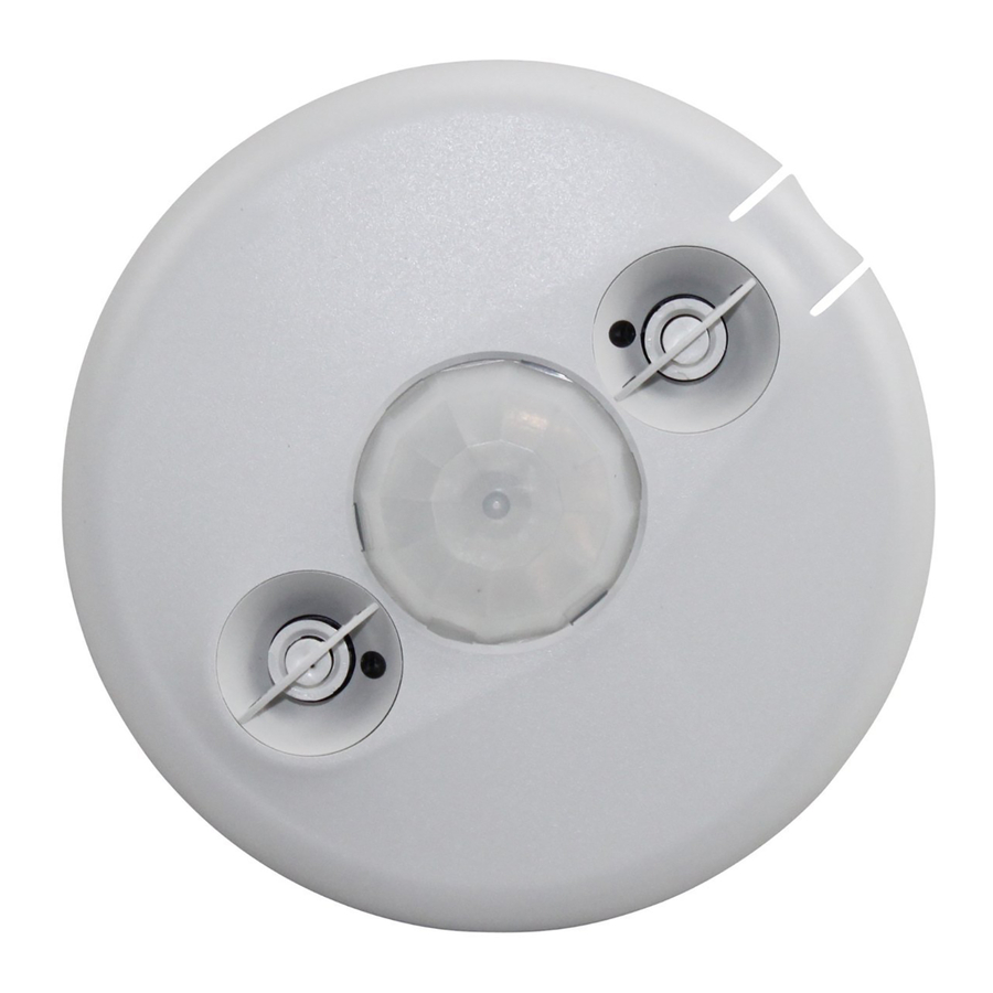
360° Dual Technology • Low Voltage
with Light Level, Isolated Relay and Manual On features
Specifications
Voltage ..........................18-28VDC/VAC, half wave rectified AC
Current Consumption .........................................................43mA
Power Supply ....................................Watt Stopper Power Packs
Isolated Relay Rating ........................................ 1A @30VDC/VAC
Operating Temperature .......................32° to 131°F (0° to 55°C)
Light Level One-Step Adjustment .........................10FC—300FC
Time Delay Adjustment .......................................5 to 30 minutes
Walk-Through Mode ...............................................3 minutes
Test Mode ..................... 5 seconds (after power-up or reset)
PIR Coverage (Typical) .....................................................1000 ft
Sensitivity Adjustment .............. Auto or Low (switch setting)
Ultrasonic Coverage (Typical) ..........................................1000 ft
Sensitivity Adjustment .........................Min. to Max. (trimpot)
Frequency...................................................................... 40kHz
DT-300
Occupancy Sensor
2
2
U.S. Patents: 4,787,722
5,189,393
and Patent Pending
Advertisement
Table of Contents

Related Manuals for wattstopper DT-300


Summary of Contents for wattstopper DT-300
- Page 1 DT-300 360° Dual Technology • Low Voltage Occupancy Sensor with Light Level, Isolated Relay and Manual On features Specifications Voltage ......18-28VDC/VAC, half wave rectified AC Current Consumption ............43mA Power Supply ........Watt Stopper Power Packs Isolated Relay Rating ........1A @30VDC/VAC Operating Temperature .......32°...
-
Page 2: Unit Description
The DT-300 turns lighting systems on and off based on occupancy. The DT-300 provides numerous operating modes that can be combined to create the ideal custom control. -
Page 3: Placement Guidelines
4 to 6 feet away from air supply vents. Mount the sensor to the ceiling. The DT-300 is designed for a ceiling height of about 8-10 feet. Mounting above or below this range will signifi cantly affect the coverage patterns. - Page 4 If the space is larger than 30’ x 30’ it will be necessary to use more than one sensor to ensure complete coverage. Coverage 30 ft (9.14m) Ultrasonic Overlap Ultrasonic Coverage 30 ft (9.14m) Sensor Ultrasonic Overlap Call 800.879.8585 for Technical Support...
-
Page 5: Wiring Directions
TURN POWER OFF AT THE CIRCUIT BREAKER BEFORE INSTALLING POWER PACKS, SWITCHES OR SENSORS. Each Watt Stopper B series power pack can supply power for up to 2 DT-300 sensors. Each Watt Stopper BZ series power pack can supply power for 3 DT-300 sensors. When... -
Page 6: Connecting Wires
Low Voltage Load #2 Class 2 (Optional) Line Black Voltage Common Blue Control Out +24V Ceiling Depluggable Terminal Spring Clips (2) Rear Housing Line Voltage Switches Front Cover DT-300 Standard wiring with local off switch Call 800.879.8585 for Technical Support... - Page 7 For low voltage momentary switch set DT-300 DIP switches: Front Cover 1 = Off 2 = On DT-300 3 = On Manual-On wiring with low voltage momentary switch Manual-On wiring with low voltage momentary switch Visit our website for FAQs: www.wattstopper.com...
-
Page 8: Mounting The Sensor
MOUNTING THE SENSOR Directly to Ceiling 1. Attach the plastic spring clips to the edge of the sensor in the slots Ceiling provided. 2. Cut a 3.5” to 4” round hole in the acoustic ceiling tile at the Depluggable terminal mounting location. -
Page 9: Sensor Adjustment
SENSOR ADJUSTMENT This unit is pre-set for basic operation as described in this guide. Adjustment is optional. The sensors are factory preset to allow for quick installation in most applications. Verifi cation of proper wiring or coverage, or customizing the sensor’s settings can be done using the following procedures. -
Page 10: Dip Switches
DIP SWITCHES Occupancy Logic: Switches 1, 2, 3 Logic Confi guration Chart The DT-300 has 8 logic confi gurations for occupancy triggers. Determine the appropriate Occupancy Logic Option using the Trigger matrix, then set the DIP switches accordingly. Trigger Initial Occupancy: The method that activates a change... - Page 11 PIR Sensitivity: Switch 8 • Minimum forces a reduced detection range for the PIR. • Max./SmartSet causes the DT-300 to monitor the controlled environment and automatically select the maximum sensitivity that will provide reliable operation without false detection. This setting is constantly updated.
-
Page 12: Troubleshooting
If 24VDC is present and the relay is not closing, replace the power pack. • If 24VDC is not present, check for a break in the low voltage wiring. Visit our website for FAQs: www.wattstopper.com... - Page 13 Lights do not turn off automatically. Green LED Reduce ultrasonic sensitivity by turning adjustment pot counter- fl ashes clockwise until it only fl ashes when movement occurs. Red LED Check to see if you have used the Manual Switch connection. Do not fl...
-
Page 14: Ordering Information
Auxiliary Relay Pack: 120/277VAC, 60Hz, 20A Ballast 347VAC, 60Hz, 15A Ballast All sensors are white. B series power packs supply power for up to 2 DT-300 sensors. BZ series power packs supply power for up to 3 DT-300 sensors. WARRANTY INFORMATION Watt Stopper/Legrand warranties its products to be free of defects in materials and workmanship for a period of fi...
Need help?
Do you have a question about the DT-300 and is the answer not in the manual?
Questions and answers