Table of Contents
Advertisement
Available languages
Available languages
No: 24261 – 09/16 rev. 1
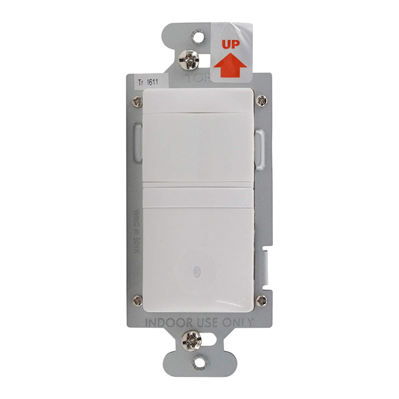
Catalog Number • Numéro de Catalogue • Número de Catálogo: RH-250
Country of Origin: Made in China • Pays d'origine: Fabriqué en Chine • País de origen: Hecho en China
RH-250 Multi-way Wall Switch Convertible Occupancy Sensors are designed to replace standard single pole and multi-way (3-way, 4-way)
switches. They are ideal for any room with multiple entries and any other indoor space where vacancy sensor-based controls with manual ON/
OFF capability are desirable.
Like standard switches, you can press the ON/OFF button to turn the light or fan (controlled load) ON and OFF. Unlike standard switches, the
RH-250 automatically turns OFF the controlled load after the coverage area has been vacant for a period of time (Time Delay). If motion is
detected within 30 seconds after it automatically turns OFF, the RH-250 automatically turns the load back ON.
While the sensor is factory preset as a Vacancy Sensor with manual ON operation, it can be adjusted to work as an occupancy sensor that turns
the controlled load ON automatically upon detection of occupancy in the area.
The RH-250 can be wired with up to three additional RH-250s for multi-way Manual/Auto–ON/OFF of one or several loads (up to one load
connected to each RH-250). It can also be wired to up to four RH-253 single pole momentary wall switches for multi-way Manual-ON/OFF
Automatic-OFF control of one load.
Lighted Switch
To help you locate the RH-250 in a dark room, the amber LED illuminates the ON/OFF button while the controlled load is OFF. When the
controlled load is ON, the LED is OFF.
Operating Modes
For multi-way operation of two or more RH-250s, we recommend that the Operating Mode be the same in all sensors related to the same load.
This makes it easier to understand the multi-way control operation as well as trouble shooting. There are two operating modes to select from:
MODE 1 Vacancy sensor (Manual-ON/OFF, Auto-OFF): The user must press the ON/OFF button to turn the load ON. The RH-250 keeps the
load ON until no motion is detected by any of the related RH-250s for the time delay period. There is also a 30 second reset delay after the
automatic shut-off. If motion is detected during this time, the sensor turns the load back ON automatically. After the 30 second reset delay has
elapsed, the ON/OFF button must be pressed to turn ON the load.
MODE 2 Occupancy sensor (Auto-ON/OFF with manual control and reset to auto after 5 minutes of vacancy): The load turns ON and OFF
automatically based on occupancy detection. Once turned ON the RH-250 keeps the load ON until no motion is detected by any of the related
RH-250s for the time delay period. If the load is turned OFF manually, automatic-ON is re-enabled when no motion is detected for 5 minutes.
This prevents the load from being turned ON after it was deliberately turned OFF.
Time Delay
The time delay can be selected by the user during set up. It can be adjusted to any of these fixed values:15 seconds/5 minutes/15 minutes/30
minutes. We recommend that the time delay be the same in all sensors related to the same load. This makes it easier to understand the multi-
way control operation as well as trouble shooting. For additional information on how to adjust it, please read the SENSOR ADJUSTMENT &
PROGRAMMING section of this installation manual.
Light Level
When the operating mode is set for occupancy sensor, Mode 2 (Auto-ON) this feature prevents the sensor from automatically turning the lights
ON if there is already enough light in the area.
In a multi-way application, each sensor monitors the light level at it's location. If any sensor related to the load detects motion AND the measured
light level in that sensor's area is lower than it's Light Level setting, the load turns ON.
To adjust the light level, please read the SENSOR ADJUSTMENT & PROGRAMMING section of this installation manual.
Wattstopper
Multi-Way Wall Switch Convertible Occupancy Sensor
Détecteur de présence multivoies à interrupteur mural convertible
Sensor de Desocupación de pared configurable
Installation Instructions • Instructions d'Installation • Instrucciones de Instalación
Voltage .........................................................................120VAC, 60Hz
Load (Multi-Way)
Time Delay Adjustment .................... 15 sec., 5 min., 15 min., 30 min.
Light Level Adjustment ..................................................10 fc to 150 fc
Environment ................................................................Indoor use only
Tools Needed
DESCRIPTION AND OPERATION
®
SPECIFICATIONS
Incandescent or fluorescent ....................................... 0-600 Watts
Fan motor ............................................................................ 1/6 hp
Operating Temperature.......................... 32° to 131°F (0° to 55°C)
Humidity................................................ 95% RH, non-condensing
Insulated Screwdriver
Wire Strippers
Advertisement
Table of Contents

Related Manuals for wattstopper RH-250


Summary of Contents for wattstopper RH-250
-
Page 1: Specifications
Automatic-OFF control of one load. Lighted Switch To help you locate the RH-250 in a dark room, the amber LED illuminates the ON/OFF button while the controlled load is OFF. When the controlled load is ON, the LED is OFF. -
Page 2: Installation And Wiring
“Strip Gauge,” in Fig. 3. (approx. 1/2 inch). Fig. 3: Wire Stripping 4. Wire the sensor Twist the existing wires together with the wire leads on the RH-250 sensor(s) as indicated in either step 4a or 4b. Cap wires securely using wire nuts. Yellow – Traveler 2 Yellow –... - Page 3 Wiring one RH-250 and one RH-253 single pole 120V/60Hz momentary switch for multi-way Manual-ON/OFF single Neutral load control. Load IMPORTANT: The RH-250 must be installed in the wiring wall box that White Neutral White connects to the load. Black...
-
Page 4: Test Mode
4. Repeat as necessary to ensure that the desired coverage areas are within detection range. You can do this test for each RH-250 in your multi-way configuration. So that you can determine the actual coverage area for each multi-way switch individually, only the RH-250 that is in TEST mode will control the load. -
Page 5: Caractéristiques
Interrupteur lumineux Pour vous aider à localiser le RH-250 dans une pièce sombre, la DEL ambrée illumine le bouton marche/arrêt lorsque la charge contrôlée est éteinte. Lorsque la charge contrôlée est active, la DEL est éteinte. Modes de fonctionnement Pour le fonctionnement multivoies de deux RH-250 ou plus, nous recommandons d’utiliser le même mode de fonctionnement pour tous les... -
Page 6: Installation Et Câblage
IMPORTANT: le RH-250 doit être installé dans la boîte de câblage murale qui est connectée à la charge. • Raccordez le fil de TERRE (cuivre) non isolé de chaque boîte de câblage au circuit à la borne verte de chaque RH-250 et RH-253. - Page 7 Jaune – Va-et-vient 2 vers RH-253 • Raccordez le fil VA-ET-VIENT 1 en provenance de la boîte Va-et-vient 1 Rouge – Charge de câblage du RH-253 au fil noir du RH-250. vers RH-250 (alimentation Circuit (alimentation\ fournie à la lampe •...
-
Page 8: Mode Test
à la lumière ambiante actuelle. 6. Répétez le processus (en commençant par l’étape 1) pour chaque RH-250 de votre configuration multivoies jusqu’à ce que le niveau de luminosité soit réglé correctement pour chacun d’entre eux. -
Page 9: Especificaciones
Interruptor Iluminado Para facilitar la ubicación del RH-250 en un cuarto oscuro, un LED color ámbar ilumina el botón de ENCENDIDO/APAGADO cuando la carga controlada se encuentra apagada. Cuando por el contrario esta última se encuentra encendida, el LED estará apagado. - Page 10 • Conecte el cable verde (o alambre de cobre sin aislante) que conecta a TIERRA a la terminal verde del RH-250 y del RH-253. • Conecte el cable de conexión a NEUTRO del circuito y de la lámpara o ventilador (CARGA) al cable blanco del RH-250.
- Page 11 3. Mueva la perilla de Ajuste de Nivel de Luz Natural a su valor mínimo (completamente en sentido contrario a las manecillas del reloj) en el RH-250 que usted este ajustando. Salga de la habitación y deje que el sensor apague las luces después del retardo de apagado de 15 segundos.
-
Page 12: Solucion De Problemas
5. Repita este proceso (empezando con el paso 1) para cada RH-250 en su cableado tipo 3 o 4 vías hasta que el Nivel de Luz Natural haya sido ajustado apropiadamente en cada uno de los sensores.
Need help?
Do you have a question about the RH-250 and is the answer not in the manual?
Questions and answers