Advertisement
2006-2008 SUZUKI M109R / C109R
Parts List
1
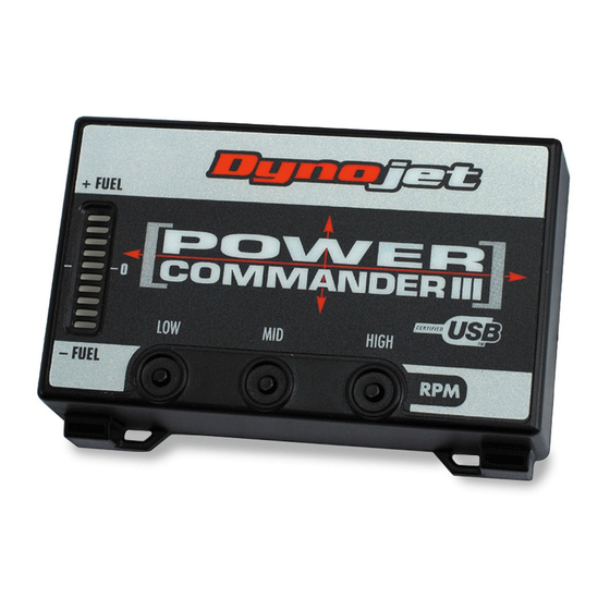
Power Commander
1
Installation Guide
1
USB cable
1
CD-ROM
1
Power adapter
2
Dynojet decals
2
Power Commander decals
2
Velcro® Strip
1
Alcohol Swab
1
Port plug set
You can also download the
Power Commander software and
latest maps from our web site at:
www.powercommander.com
PLEASE READ ALL DIRECTIONS BEFORE STARTING INSTALLATION
Dynojet Research 2191 Mendenhall Drive North Las Vegas, NV 89081 (800) 992-4993
330-411
www.powercommander.com
Installation Instructions
THE IGNITION MUST BE TURNED OFF BEFORE INSTALLATION!
06-08 Suzuki M109R- 1
Advertisement
Table of Contents

Subscribe to Our Youtube Channel
Related Manuals for Dynojet Power Commander 3


Summary of Contents for Dynojet Power Commander 3
- Page 1 2006-2008 SUZUKI M109R / C109R Installation Instructions Parts List Power Commander Installation Guide USB cable CD-ROM Power adapter Dynojet decals Power Commander decals Velcro® Strip Alcohol Swab Port plug set You can also download the Power Commander software and latest maps from our web site at: www.powercommander.com THE IGNITION MUST BE TURNED OFF BEFORE INSTALLATION! PLEASE READ ALL DIRECTIONS BEFORE STARTING INSTALLATION Dynojet Research 2191 Mendenhall Drive North Las Vegas, NV 89081 (800) 992-4993 330-411 www.powercommander.com...
- Page 2 Remove the main seat and both side covers. Remove the fuel tank. Remove the air box. There are several hoses going into the air box. We recommend referring to the service manual for proper removal and installation. Route the wiring harness from the PCIII behind the left hand side of the frame and go towards the throttle bodies (Fig. A). Unplug Unplug the stock wiring harness from each injector (Fig. B). Unplug Plug the connectors from the PCV inline of the stock injectors and the stock wiring harness (Fig.C). Orange - cylinder 1- front Yellow - cylinder 2 - rear...
- Page 3 Unplug the Throttle Position Sensor connector (Fig. D). Unplug This connector is located on the right hand side of the throttle bodies and is GREY in color. Plug the PCIII connectors in-line of the stock wiring harness and TPS Route the ground wire from the PCIII thru Ground the front hole in the battery box. 10 Attach the ground wire from the PCIII to the negative side of the battery (Fig. E). 11 Install the PCIII under the left hand side cover. Zip tie the unit to the metal brace near the ECU (Fig. F). 12 Reinstall air box and fuel tank. 330-411 www.powercommander.com 06-08 Suzuki M109R - 3...
- Page 4 13 Plug the Dynojet O2 eliminator into the stock wiring harness. 14 Route the O2 eliminator harness to the inside of the frame near the thermostat housing (Fig. G). Ground 15 Ground the other end of the Dynojet O2 eliminator to the bolt of the thermostat housing (Fig. H). 16 Secure the PCIII in the tail section using the supplied velcro. Make sure to use the alcohol swab to clean both surfaces before attaching. 17 Bolt the fuel tank back into place. Reinstall the fairing and seats. 330-411 www.powercommander.com 06-08 Suzuki M109R - 4...
Need help?
Do you have a question about the Power Commander 3 and is the answer not in the manual?
Questions and answers