Advertisement
I n s ta l l a t i o n I n s t r u c t i o n s f o r :
Parts List
1
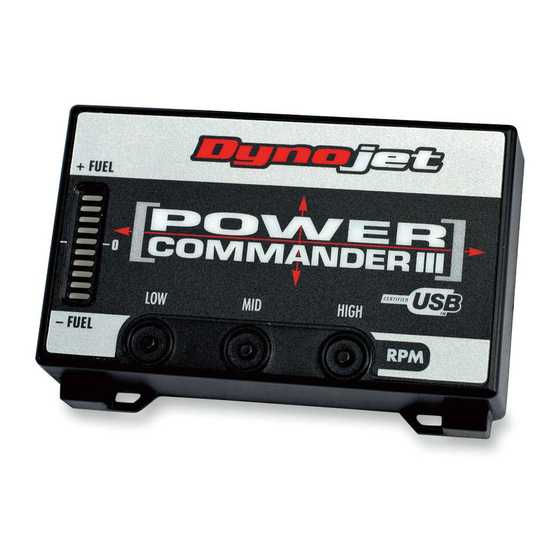
Power Commander
1
USB Cable
1
CD-ROM
1
Installation Guide
1
Power Adapter
2
Wire T ap
1
Power Wire
2
Power Commander Decals
2
Dynojet Decals
1
Velcro
Strip
®
1
Alcohol Swab
The ignition MUST be turned
OFF before installation!
You can also download the Power
Commander software and latest maps
from our web site at:
www.powercommander.com
PLEASE READ ALL DIRECTIONS BEFORE STARTING INSTALLATION
Dynojet Research 2191 Mendenhall Drive North Las Vegas, NV 89081 (800) 992-4993 www.powercommander.com
i109-411
2 0 0 2 - 2 0 0 4 H o n d a V T X 1 8 0 0 C
2 0 0 2 - 2 0 0 3 H o n d a V T X 1 8 0 0 R
Button Adjustment Display
F o r 0 4 - 0 7 R & N m o d e l u s e 1 2 2 - 4 11
F o r 0 5 - 0 7 F & C m o d e l u s e 1 2 2 - 4 11
Faceplate Buttons
Expansion Port
USB Port
VTX 1800 - PCIII USB - 1
Advertisement
Table of Contents

Summary of Contents for Dynojet Power Commander III USB 109-411
- Page 1 You can also download the Power Commander software and latest maps from our web site at: www.powercommander.com PLEASE READ ALL DIRECTIONS BEFORE STARTING INSTALLATION Dynojet Research 2191 Mendenhall Drive North Las Vegas, NV 89081 (800) 992-4993 www.powercommander.com i109-411 VTX 1800 - PCIII USB - 1...
- Page 2 Remove the seat. Remove both side covers. Disconnect the black connector from the ECU (Fig. A). Unplug this connector Plug the connectors from the Stock connector Power Commander in line of this connector and the ECU (Fig. B). NOTE: The connectors on the Power Commander III USB are black.
- Page 3 Locate the red wire with a Location: T op of ECU yellow tracer on the grey Red wire with yellow tracer 3rd pin from right connector side of the ECU. Connect the supplied wire tap to this connector. Make sure the tap is completely closed (Fig.
- Page 4 Locate the brown wire which connects to a brown wire with a Red wire from PCIII black tracer (this is the power for the tail light). Plug the red wires from the Power Commander in line of this connection (Fig. G). Route the Power Commander between the tray and the left hand frame rail.
- Page 5 Follow these additional instruc- tions for European models only. Supplied power lead Red wire from PCIII Plug the supplied power lead to the red wire of the PCIII (Fig. J). Locate the black wire with a white tracer on the grey connec- tor side of the ECU (Fig.


Need help?
Do you have a question about the Power Commander III USB 109-411 and is the answer not in the manual?
Questions and answers