Table of Contents
Advertisement
Quick Links
Parts List
1
Power Commander
1
USB Cable
1
Wire Tap
1
CD-ROM
1
Installation Guide
1
Power Adapter
2
Power Commander Decals
2
Dynojet Decals
1
Wire tap
2
Velcro
Strip
®
1
Alcohol Swab
The ignition MUST be turned
OFF before installation!
You can also download the Power
Commander software and latest maps
from our web site at:
www.powercommander.com
PLEASE READ ALL DIRECTIONS BEFORE STARTING INSTALLATION
Dynojet Research 2191 Mendenhall Drive North Las Vegas, NV 89081 (800) 992-4993 www.powercommander.com
i437-411
www.powercommander.com
2008 Yamaha Tmax 500
Installation Instructions
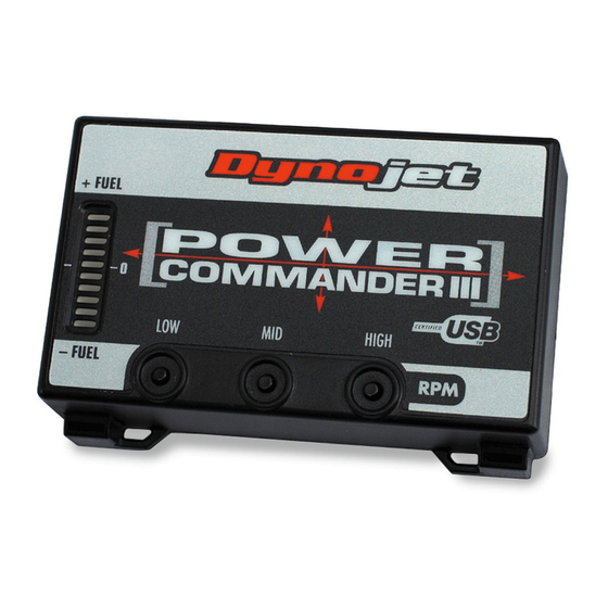
Button Adjustment Display
Faceplate Buttons
Expansion Port
2008 Yamaha Tmax 500 - PCIII USB - 1
USB Port
Advertisement
Table of Contents

Subscribe to Our Youtube Channel
Related Manuals for Dynojet POWER COMMANDER 3


Summary of Contents for Dynojet POWER COMMANDER 3
- Page 1 Commander software and latest maps from our web site at: www.powercommander.com PLEASE READ ALL DIRECTIONS BEFORE STARTING INSTALLATION Dynojet Research 2191 Mendenhall Drive North Las Vegas, NV 89081 (800) 992-4993 www.powercommander.com i437-411 www.powercommander.com 2008 Yamaha Tmax 500 - PCIII USB - 1...
- Page 2 Remove the bodywork panels shown in Figure A. Remove the front fairing panel to access the battery. Remove Remove the panel shown in Figure B. Remove PCIII Install the PCIII next to the battery (Fig. C). Attach the ground wire of the PCIII to the negative side of the battery.
- Page 3 Route the PCIII harness down the right side following the stock wiring Guides harness.- Use the 2 stock plastic ties to secure the PCIII harness (Fig. D) PCIII harness Locate the black rubber cover on the right hand side of the scooter that contains the injector connectors (Fig.
- Page 4 Plug the PCIII connectors in line with the stock injector connectors (Fig. G). The PCIII ORANGE wires go to the GREEN connector for cylinder #1. The PCIII YELLOW wires go to the BLACK connector for cylinder #2. Locate the Throttle Position Sensor on the right side of the throttle body, below the air filter cover (Fig.
Need help?
Do you have a question about the POWER COMMANDER 3 and is the answer not in the manual?
Questions and answers