Advertisement
Quick Links
Jacket-less, Gas-fired, Balanced-flue, Power-vented, Air heater
This document applies when installing into an air handler or as part of an air handling
Please read this document carefully prior to commencing building into an air handler
®
Application instructions
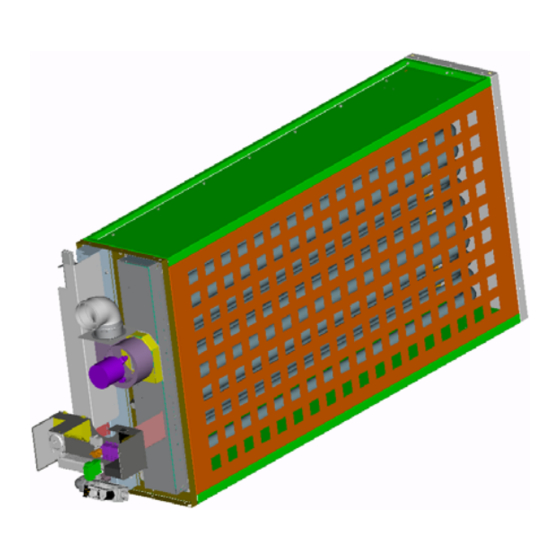
RHC 8000
RHC 8000
system
These appliances meet the following EC Directives
Dir. 2009/142/EC:GAD
Dir. 2004/108/EC:EMC
Dir. 2006/95/EC:LVD
Dir. 2006/42/EC:MD (annexe ll, sub B)
Reznor Europe N.V.
(M) RJL
(M) DJL
– J.& M. Sabbestraat 130 – B 8930 Menen
Tel +32 56 529 511 – fax +32 56 529 533
0710RHC8-JLNLEN
Subject to modifications
Advertisement

Related Manuals for Reznor RHC 8000 RJL


Summary of Contents for Reznor RHC 8000 RJL
- Page 1 Dir. 2006/42/EC:MD (annexe ll, sub B) Please read this document carefully prior to commencing building into an air handler Subject to modifications Reznor Europe N.V. – J.& M. Sabbestraat 130 – B 8930 Menen Tel +32 56 529 511 – fax +32 56 529 533...
- Page 2 (Directive 2006/42/EC (annex ll, Sub B) PROHIBITION TO PUT INTO SERVICE Reznor Europe N.V. J & M Sabbestraat 130 B 8930 Menen Belgium Herewith declares that: Power-vented gas-fired air heaters, type: RHC 8000 RJL DJL series Models 8050 06 8030 06 8125M.15 8075-09 8045 09 8150M.18...
- Page 3 INDEX ......................2 ECLARATION STATEMENT ........................4 EFINITIONS .......................4 ASIC INFORMATION ....................9 RACTICAL APPLICATION ....................10 IMITATIONS FOR USE & ..................12 URNER CONTROLS SECTION ......................13 AS CONNECTION ....................14 LECTRICAL EQUIPMENT 8000(M) ...............14 OMBUSTION CIRCUIT RHC 8000(M) ...............17 OMBUSTION CIRCUIT RHC ..................20 RESSURE DROP INFORMATION ..............23 EATING SECTION WITH BY PASS CHANNELS...
-
Page 4: Basic Information
1.0 D EFINITIONS ASIC INFORMATION Jacket-less: instructions contained this A gas-fired air heater supplied as a skeleton document apply to the models RHC appliance e.g. without case or cover. 8000(M) RJL/DJL gas fired fan assisted warm air heaters. Module: The jacket-less gas-fired air heater. Models RHC 8000(M) RJL are intended for use in appliances as outdoors (roof Constructor:... - Page 5 Dimensions Figure 1 : Side view Figure 1a: RHC 8000 DJL/RJL (not 8125, 8150, 8175,8200) (n° 59014_01) Figure 1b: RHC 8125M, 8150M, 8175M DJL/RJL Figure 1c: RHC 8200M DJL/RJL (n° 59710_01) (n° 59706_01 a) 1. Gas connection 2. Flue outlet Electrical connection 0710RHC8-JLNLEN 5/36...
- Page 6 Figure 2 : Top view Figure 2a: RHC 8000 DJL/RJL ( (not 8125, 8150, 8175,8200) (n° 59014_02) Figure 2b: RHC 8125M, 8150M, 8175M DJL/RJL (n° 59710_02) Figure 2c: RHC 8200M DJL/RJL (n° 59706_02 a) 0710RHC8-JLNLEN 6/36...
- Page 7 Figure 3a : Front view RHC 8000 DJL/RJL (n° 59012_03) Dimensions applicable to models RHC 8000 (not 8125, 8150, 8175,8200) (see fig. 1a - 2a & 3a) RHC 8000 DJL/RJL RHC 8000 DJL RHC 8000 RJL Type 8030 06 1244 8045 09 1244 8050 06...
- Page 8 Figure 3b: Back side view RHC 8125M, 8150M &8175M DJL/RJL (n° 59710_03) Figure 3c: Back side view RHC 8200M DJL/RJL (n° 59706_03) Dimensions applicable to model RHC 8000M (see fig. 1b/1c –2b/2c & 3b/3c) RHC 8000 M DJL/RJL Type 8125M.15 1272 1089 8150M.18...
-
Page 9: Practical Application
Weights (kg) ( table 1) Type 8030 06 8045 09 8050 06 8060 12 8075 09 8075 15 8090 18 8100 12 Unit Packaging Total Type 8125M.15 8150M.18 8175M.21 8200M.24 Unit Packaging Total RACTICAL PPLICATION Figure 4 : Compartment dimensions For horizontal airflow Heat exchanger compartment size. - Page 10 Figure 5 : Installation possibilities for RHC 8000(M) air heater modules Always ensure that the inlet perforated profile plate (when required) is installed at the air ‘inlet’ side of the heat exchanger as shown in figure 5 4.0 L IMITATIONS FOR Heat exchanger compartment 4.1.1 Minimum airflow requirement through heat exchanger enclosure : RHC 8000(M) RJL &...
- Page 11 Maximum airflow through heat exchanger 4.1.2 Table 3 indicates the heat output (kW) of the enclosure different models. Special attention must be given to ensure that the temperature rise of the air, The maximum allowable airflow [through the passing through the enclosure around the enclosure (duct channel) around the tubes] can heat exchanger tubes, is high enough to be calculated as follows :...
- Page 12 Part or the whole of the tubes may Warning become damaged or can be the source of Use of RHC 8000(M) heating modules poor combustion if the air velocity as for purposes other than those described recommended above is not applied. above could result in severe personal injury or death and cause property damage.
-
Page 13: Gas Connection
CAUTION : ONNECTION Alterations to the burner and/or its controls, any ¾” or R 1 ¼”) other electrical apparatus supplied as part of the heating module or changing of the settings as supplied is strictly forbidden. To do so is in Attention : All RHC 8000M units are designed contravention of the E.C. -
Page 14: Electrical Equipment
LECTRICAL QUIPMENT OMBUSTION SYSTEM 8000( ‘ ’ OUTDOOR Warning : Ensure that when installing electrical wiring or cables no contact is made with the 8.1.1 Inlets for combustion air and flue outlets burner, heat exchanger or flue arrangement. shall be so designed so that when an Cables or wires must be securely fixed so that appliance finally... - Page 15 Ensure the combustion inlet grill at the The 90° elbow, sealing ring, terminal and the control door panel is completely sealed to combustion air inlet protection grill must be prevent ingress of water. installed according to figure 7. It is forbidden to use the combustion inlet All sealings must be correctly placed in the grill as passage for cables or gas tubes to avoid flowing back of combustion...
- Page 16 Figure 8 ASSURE THE SEALING OF THE COMBUSTION AIR INLET GRILL TO THE CONTROLS COMPARTMENT SIDE PANEL IS WATERTIGHT (n° 59008_03) Figure 9: Controls compartment (side) panel for RHC 8000(M) RJL units HOLE (∅112mm or ∅142mm) REQUIRED TO RECEIVE SEALRING (PN 06 22786 104 or 06 22786 134) OPENING REQUIRED TO FIT COMBUSTION AIR INLET GRILL...
- Page 17 8.1.3 The terminal outlet (PN 60 50712 300) of thick OMBUSTION SYSTEM wall aluminium pipe supplied must be fitted in RHC 8000(M) DJL ‘INDOOR’ a horizontal plane and be placed so as to fit exactly between the elbow on the combustion fan and the outlet terminal hole with sealing 9.1.1 The DJL Modules are provided with flue...
- Page 18 Table 6 : 9.1.4 The combustion air inlet duct must not pass Centre distances combustion air inlet flue through the cabinet panel by more than 50 outlet Model Centre Cabinet hole Connection Ø distance B size 9.1.5 When the DJL model is to be used as a type (mm) (mm) required for...
- Page 19 Figure 11a : Combustion air inlet - outlet dimension requirements Combustion air inlet pipe Flue outlet pipe Teflon sealing ring 90° bend Gas passage grommet vinly Rc ¾” or Rc 1 ¼”(PN 06 22783 125 or 06 22783 054) Not delivered with the unit (n°...
- Page 20 10.0 P RESSURE LOSS THROUGH HEATING MODULE 10.1 The charts below indicate the pressure exchanger enclosure (see fig. 4 and table drop over the heating module versus the flow volume through heat 10.2 The temperature rise ( T) shown is for 100% heat output.
- Page 21 Figure 12c : Pressure losses through RHC8000M. module RHC8175M.21 RHC8200M.24 20100 m³/h 23300 m³/h 21500 m³/h 24000 m³/h 16000 20000 24000 28000 32000 36000 40000 44000 48000 52000 Airflow (m³/h) through the heat exchanger enclosure ΔT ΔT Figure 12d : Pressure loss through a single RHC8000 module RHC8075-15 RHC8090-18...
- Page 22 Figure 12e : Pressure losses through a RHC8000M. module RHC8125M.15 RHC8150M.18 18200 m³/h 15600 m³/h 18000 m³/h 21000 m³/h 14000 16000 18000 20000 22000 24000 26000 28000 30000 32000 34000 36000 38000 40000 Airflow (m³/h) through the heat exchanger enclosure ΔT 24 23 22 21 ΔT...
- Page 23 11.0 H A) The by-pass can either be mounted on top of the EATING SECTION WITH BY PASS heat exchanger or besides the heat exchanger as CHANNEL in figure 13 shown The recommended maximum by-pass dimensions for a given air flow (V ) can be calculated as 11.1 By-pass requirements...
- Page 24 As explained above, the air flow V through Note In this case 2. m³/s flows through the heat exchanger enclosure must be used in (= 10750m³/h) the heat exchanger enclosure. figure 12 to extract the correct total pressure The remaining 2. m³/s flows through drop over the RHC module with by-pass.
- Page 25 Figure 13a : FRONT VIEW Figure 13b : SIDE VIEW 0710RHC8-JLNLEN 25/36...
- Page 26 12.0 I Table 8a NSTALLATION OF UNITS IN Minimum airflow requirements for 2 RHC SERIES units in series : Model 12.1 General (m ³ /h) (m ³ /h) 2x 8030 06 3750 4400 12.1.1 Two or three RHC units can be installed in 2x 8045 09 5650 6600...
- Page 27 Pressure drop for 2 units in series Figure 14a Pressure losses through 2 RHC8000 heating modules in serie 2x RHC8050-06 2x RHC8075-09 2x RHC8100-12 12400 m³/h 9300 m³/h 6200 m³/h 14300 m³/h 10790 m³/h 7150 m³/h 5000 7000 9000 11000 13000 15000 17000...
- Page 28 Figure 14c Pressure losses through 2 RHC 8000 heating modules in series 2x RHC8075-15 2x RHC8090-18 11200 m³/h 9300 m³/h 14300 m³/h 11900 m³/h 8000 10000 12000 14000 16000 18000 20000 22000 24000 Airflow (m³/h) through the heat exchanger enclosure ΔT 2x RHC8075-15 ΔT 2x RHC8090-18 Figure 14d...
- Page 29 Figure 14e Pressure losses through 2 RHC8000M in series 2x RHC8175M.21 2x RHC8200M.24 23300 m³/h 20100 m³/h 21500 m³/h 24000 m³/h 16000 20000 24000 28000 32000 36000 40000 44000 48000 52000 Airflow (m³/h) through the heat exchanger enclosure 50 47 44 42 40 38 36 32 31 30 29 28 27 26 ΔT 2x ΔT 2x RHC8200M.24...
- Page 30 Figure 14g Pressure losses through 3 RHC8000 heating modules 3x RHC8030-12 3x RHC8045-09 3x RHC8060-12 10500 m³/h 7850 m³/h 5250 m³/h 4000 6000 8000 10000 12000 14000 16000 Airflow (m³/h) through the heat exchanger enclosure 50 48 46 44 42 40 38 ΔT 3xRHC8030-06 50 48 46 ΔT 3xRHC8045-09...
- Page 31 Figure 14i Pressure losses through 3 RHC8000M modules in series 3x RHC8125M.15 3x RHC8150M.18 3x RHC8175M.21 3x RHC8200M.24 22000 m³/h 26000 m³/h 30000 m³/h 35000 m³/h 20000 22000 24000 26000 28000 30000 32000 34000 36000 38000 40000 42000 44000 46000 48000 50000 52000 Airflow (m³/h) through heat exchanger enclosure ΔT 3x 50 48 46...
- Page 32 12.4 Multiple heating sections in series with by-pass channels (not applicable for RHC 8000M models) 12.4.1 By-pass requirements : b) By-pass on top of heat exchanger : * Referring to section 4.1.3, a by-pass duct parallel with heat exchanger Model dim.
- Page 33 Figure 15 : Installation of air fan 12.4.3 Calculation of alternative by-pass dimension: Due to space restrictions it may not be possible to use the above mentioned maximum dimension by-pass. In this case a smaller by-pass can be applied. Obviously, this smaller by-pass will result in a higher portion of the total airflow through the heat exchanger enclosure and consequently in a higher total pressure drop...
-
Page 34: Flue Outlet
14.0 NSTALLATION OF MULTIPLE RHC…. DJL UNITS WITH VERTICAL not applicable for FLUE OUTLET RHC 8000M models * unit 4 : proceed as follow (see drw 3): Install on the collar of the combustion 14.1 Attention : remove the 90° elbow (mounted on ventilator outlet a 45°... -
Page 35: Technical Data
Drawing 2 Drawing 3 15.0 T ECHNICAL DATA Table 9 - Model RHC 8000(M) Specifications Gas rate Heat output Minimum Heat Power Heat input modulating output Consumption Model 2 stage output kW gros kW net m³/h kg/h 8030 06 8045 09 8050 06 8060 12 8075 09... - Page 36 Table 10 Injector size and burner pressure G25 natural gas - inlet pressure = 25 mbar Injector size Burner pressure Model Quantity (mbar) (1) marking 8030 06 8045 09 8050 06 8060 12 8075 09 8075 15 8090 18 8100 12 8125M.15 2x 10.
Need help?
Do you have a question about the RHC 8000 RJL and is the answer not in the manual?
Questions and answers