Table of Contents
Advertisement
®
®
Improper installation, adjustment, alteration, service or maintenance can
cause serious property damage, injury, or death. Read these instructions
thoroughly before installing or servicing this equipment.
Gas-fired appliances are not designed for use in hazardous atmospheres
containing flammable vapors or combustible dust, or atmospheres
containing chlorinated or halogenated hydrocarbons. See Hazard Intensity
Levels, page 2.
If you smell gas:
1. Open Windows
2. Don't touch electrical switches
3. Extinguish any open flame
4. Immediately call your gas supplier.
The use and storage of gasoline or other flammable vapors and liquids in the vicinity
of this appliance is hazardous.
Installation/Operation/Maintenance
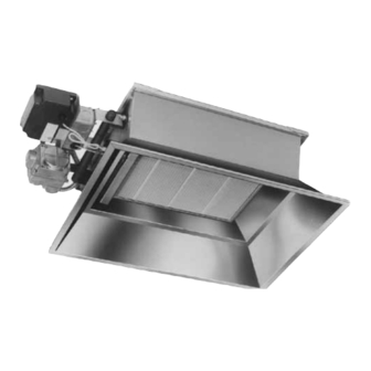
Applies to: Models RIH, RIHV, RIHVN, and RIHVL
Gas-Fired High-Intensity Infrared Heaters
Model RIH
WARNING
WARNING
FOR YOUR SAFETY
Form I-RIH (Version D)
Obsoletes Form I-RIH (Version C)
Form I-RIH, P/N 131793R8, Page 1
Advertisement
Table of Contents

Related Manuals for Reznor RIH


Summary of Contents for Reznor RIH
- Page 1 Form I-RIH (Version D) ® Obsoletes Form I-RIH (Version C) Installation/Operation/Maintenance Applies to: Models RIH, RIHV, RIHVN, and RIHVL ® Gas-Fired High-Intensity Infrared Heaters Model RIH WARNING Improper installation, adjustment, alteration, service or maintenance can cause serious property damage, injury, or death. Read these instructions thoroughly before installing or servicing this equipment.
-
Page 2: Table Of Contents
DANGER These infrared heaters are operated without venting. Comply with ventilation requirements in Paragraph 2.2, page 5. Model RIH and RIHV series heaters SHOULD NOT BE USED in the following applica- tions: • Enclosed swimming pool areas •... -
Page 3: Warranty
Both NFPA 409 (latest edition) and CAN/CSA-B149.1 (latest edition) specify a mini- mum clearance of eight feet (2.5M) from the floor to the heater in other sections, such as offices or shops, that communicate with the aircraft hangar. Form I-RIH, P/N 131793R8, Page 3... -
Page 4: Location
18 ft (5.5M) 14 ft (4.3M) 115 ft (35.1M) RIHVN 150 20 ft (6.1M) 15 ft (4.6M) 120 ft (36.6M) RIHVN 160 & RIHVN 200 24 ft (7.3M) 20 ft (6.1M) 130 ft (39.6M) Form I-RIH, P/N 131793R8, Page 4... -
Page 5: Ventilation Requirements
If damage is found, document the damage with the transporting agency and immedi- ately contact your distributor. If you are an authorized Distributor, follow the FOB freight policy procedures provided by Thomas & Betts for this product. Form I-RIH, P/N 131793R8, Page 5... -
Page 6: Dimensions And Clearances
4.0 Dimensions and Clearances 4.1 Dimensions FIGURE 1 - Model RIH Dimensions - inches and (mm) Dimensions - inches Size 30, 50, 60 15-5/16 16-5/8 14-5/8 13" 90, 100 23-15/16 25-1/4 23-1/4 (330mm) 120, 150 32-9/16 33-7/8 31-7/8 160, 200... -
Page 7: Suspending The Unit
66 (29.9) 66 (29.9) Allowable Mounting 5° - 30° 5° - 30° 5° - 30° 5° - 30° 5° - 30° 5° - 30° 5° - 30° 5° - 30° 5° - 30° Angle Tolerance Form I-RIH, P/N 131793R8, Page 7... - Page 8 "S" hooks of the short chains along the length of the long chains.. 5. Check to be sure unit is level. Crimp all "S" hooks closed Mounting Angle (A, B, C, and Form I-RIH, P/N 131793R8, Page 8...
-
Page 9: Gas Supply
Gas Valve unit are field- Gas Valve supplied. with manifold pressure tap 6” (15mm) Pressure regulator Drip Leg required when supply pressure exceeds 14” (35cm) w.c. Agency-approved Flexible Connector (if permitted by local code) Form I-RIH, P/N 131793R8, Page 9... -
Page 10: Gas Pressure
• Make electrical connection to the heater as shown in FIGURE 6A, 6B, or 6C. Form I-RIH, P/N 131793R8, Page 10... -
Page 11: Electrical Requirements By Voltage And Control Types
MV* = Mechanical Ventilation* VR* = Ventilation Relay* SW* = Ventilation Interlock Switch* (normally opened) Thermostat GGS = Green Ground Screw (+24) (inside control box) = Blue Wire – 24 VAC call for heat Form I-RIH, P/N 131793R8, Page 11... -
Page 12: Wiring Diagrams
If any of the original wire as supplied with the appliance must be replaced, it must be replaced with wiring material having a temperature rating of at least 302°F (150°C) and a minimum size of 16 AWG (1.0mm Form I-RIH, P/N 131793R8, Page 12... -
Page 13: Ignition Control
If any of the original wire as supplied with the appliance must be replaced, it must be replaced with wiring material having a temperature rating of at least 302°F (150°C) and a minimum size of 16 AWG (1.0mm2). Form I-RIH, P/N 131793R8, Page 13... -
Page 14: Ignition And Operation
• To shutdown the heater for a week or less, switch off the electrical supply to the heater. • To shutdown the heater for more than one week, switch off the electrical supply to the heater and turn off the gas supply at the gas isolation valve. Form I-RIH, P/N 131793R8, Page 14... -
Page 15: Commissioning And Startup
Adequate ventilation MUST be provided. (See Paragraph 2.2.) □ Gas piping and supply must meet requirements. (See Paragraph 6.0.) Purge air from gas supply line. □ Complete the installer record on page 20 and keep these instructions for future reference. Form I-RIH, P/N 131793R8, Page 15... -
Page 16: Accessories
Option kit includes assembled chain and "S" hooks for mounting one unit (See FIGURE 4, page 8). Gas Connector and Shutoff Valve, Option UF2 Option kit includes a 24" stainless steel gas connector and shutoff valve. Form I-RIH, P/N 131793R8, Page 16... -
Page 17: Maintenance And Service
Screw FIGURE 10 - Burner Replacement Burner Removal Instructions 1) Remove screw and slide burner backward. 2) Pull burner up and outward. Reverse the procedure to re-install burner. Ceramic Tile Burner Assembly (removed) Form I-RIH, P/N 131793R8, Page 17... -
Page 18: Troubleshooting Guide
3. Clean pilot and check pilot orifice. burner 4. Supply/manifold gas pressure too low 4. See rating plate on heater and adjust pressure. 5. Main gas orifice(s) misaligned 5. Consult sales agent or factory Form I-RIH, P/N 131793R8, Page 18... -
Page 19: Index
Troubleshooting Guide 18 Gas Supply Line 9 General 2 Ventilation Requirements 5 General Arrangement 17 Warranty 3 HAZARD INTENSITY LEVELS 2 Weight 7 Heat Deflector 16 Wire Grid 16 High Altitude 3 Wiring Diagrams 12 Form I-RIH, P/N 131793R8, Page 19... -
Page 20: Installation Record
©2012 Thomas & Betts, All rights reserved. Trademark Notes: REZNOR is registered in at least the United States. ® GAZ INDUSTRIE is registered in at least France. ® 07/12 Form I-RIH (Version D) Form I-RIH, P/N 131793R8, Page 20...
Need help?
Do you have a question about the RIH and is the answer not in the manual?
Questions and answers