Table of Contents
Advertisement
Improper installation, adjustment, alteration, service or maintenance can
cause serious property damage, injury, or death. Read these instructions
thoroughly before installing or servicing this equipment.
containing chlorinated or halogenated hydrocarbons. See Hazard Intensity
Levels, page 2.
If you smell gas:
1. Open Windows
2. Don't touch electrical switches
4. Immediately call your gas supplier.
of this appliance is hazardous.
Installation/Operation/Maintenance
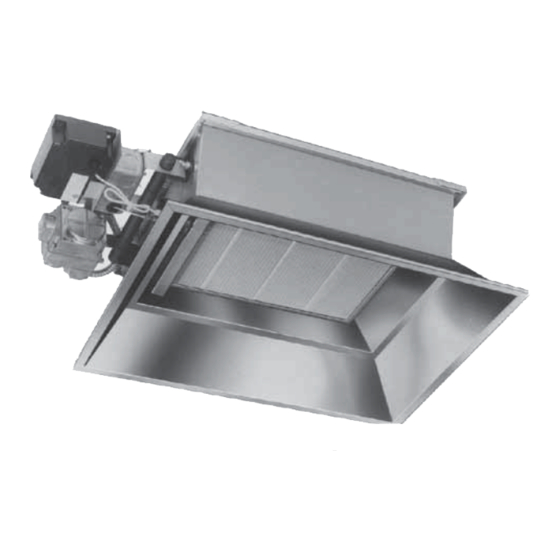
Applies to: Models RIH, RIHV, RIHVN, and RIHVL
Gas-Fired High-Intensity Infrared Heaters
Models RIH/RIHV
WARNING
WARNING
FOR YOUR SAFETY
Form I-RIH (4-16)
Obsoletes Form I-RIH (10-14)
P/N 131793R11, Page 1
Advertisement
Table of Contents


Need help?
Do you have a question about the RIH Series and is the answer not in the manual?
Questions and answers