Sign In
Upload
Download
Table of Contents
Contents
Add to my manuals
Delete from my manuals
Share
URL of this page:
HTML Link:
Bookmark this page
Add
Manual will be automatically added to "My Manuals"
Print this page
×
Bookmark added
×
Added to my manuals
Manuals
Brands
Reznor Manuals
Heater
RA150
Installation/operation/maintenance manual and reference manual
Reznor RA 150 Installation/Operation/Maintenance Manual And Reference Manual
Hide thumbs
Also See for RA 150
:
Installation & service manual
(28 pages)
1
2
3
4
5
6
7
8
9
10
11
12
13
14
15
16
17
18
19
20
21
22
23
24
25
26
27
28
29
30
31
32
33
34
35
36
37
38
39
40
41
42
43
44
45
46
47
48
49
50
51
52
page
of
52
Go
/
52
Contents
Table of Contents
Troubleshooting
Bookmarks
Table of Contents
Table of Contents
Codes and Regulations
Warranty
Installation
Use
Introduction
Safety Warnings
Secondary Heat Source
Fuels
Hazardous Atmosphere
Venting
Air for Combustion
Non-Compliance
Unpacking and Inspection
Parts Carton
Heater Placement
Minimum Clearances from Combustibles
High Altitude Installation
Fuel Tank, Pump, and Supply Lines
Fuel Tank
General Requirements
Pump
Supply Lines Installation
Typical Installation
Mounting the Heater
Weights
Suspension
Venting the Heater
Guidelines for the Vent System
Detailed Vent System Information
Draft Regulator
Installing Ducts
Inlet Air Duct
Discharge Duct
Heating Thermostat
Power Installation
Pump Power Installation
Heater Power
Heater Start-Up
System Check
Priming and Leak Check
Heater Start-Up
Start-Up Procedure
Check Test - after Start-Up
Maintenance
General Maintenance Requirements
Maintenance Schedule
Maintenance Procedures
Service
General Service
General Operation
Backflow Sensor
Oil Burner Troubleshooting
Troubleshooting
Troubleshooting Chart Guide
Location of Components Referenced in Troubleshooting Charts
Run (Green "Power On" Light Is Lit; Green "System Ready" Light Is Not Lit)
Troubleshooting Charts
With Thermostat Calling for Heat, Burner Motor Runs Momentarily
System Does Not Attempt to Ignite
Burner Ignites and Burns Steadily until System Goes into Lockout
Burner Operation Erratic/Unstable Flame Pattern
High Temperature Limit Cycles
Model RAD 250
Oil Delivery System Troubleshooting
Appendix
Wiring Diagram 230369 for Models RA/RAD 150; RA 250
Hour Meter / Cleaning Record
Index
Advertisement
Quick Links
1
Oil Burner Troubleshooting
2
Wiring Diagram 230369 for Models Ra/Rad 150; Ra 250
Download this manual
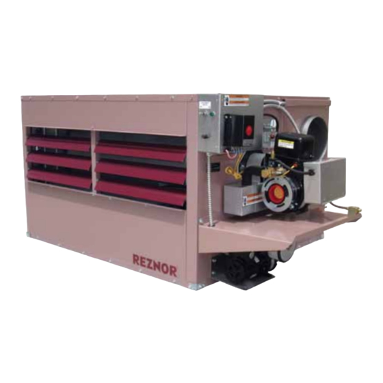
Installation/Operation/Maintenance
Heater Models
RA 150
RA 250
RAD 150
RAD 250
REZNOR
®
HEATERS AND BOILERS
Manual and
Reference Guide
CSA Certified to Electrical and Fuel Burning requirements only.
USED-OIL-FIRED
Form I-RA/RAD 150/250, P/N 234817R5, Page 1
Form I-RA/RAD 150/250
Table of
Contents
Previous
Page
Next
Page
1
2
3
4
5
Advertisement
Chapters
Table of Contents
3
Troubleshooting Chart Guide
37
Table of Contents
Troubleshooting
Troubleshooting
36
Troubleshooting Chart Guide
37
Location of Components Referenced in Troubleshooting Charts
38
Troubleshooting Charts
39
Oil delivery system troubleshooting
46
Need help?
Do you have a question about the RA 150 and is the answer not in the manual?
Ask a question
Questions and answers
Related Manuals for Reznor RA 150
Air Cleaner Reznor COLDAIR WA Series Installation & Service Manual
Evaporative coolers (28 pages)
Heater Reznor RHC 8000(m) RJL Installation, Comissioning And Servicing Instructions
Rhc 8000/8000m series rjl gas-fired, balanced-flue or power-vented unit heater (34 pages)
Heater Reznor RPV 2000 Installation Commissioning Servicing & User Instructions
(22 pages)
Heater Reznor RIH Installation Operation & Maintenance
Gas-fired high-intensity infrared heaters (20 pages)
Heater Reznor RIHL Installation Operation & Maintenance
High-intensity infrared heaters (24 pages)
Heater Reznor RA 140 Installation And Reference Manual
Used-oil-fired heaters and boilers (52 pages)
Heater Reznor RA 140 Installation/Operation/Maintenance Manual And Reference Manual
Used-oil-fired heaters and boilers (52 pages)
Heater Reznor RIH Series Installation Operation & Maintenance
Gas-fired high-intensity infrared heaters (20 pages)
Heater Reznor RIHN 30 Installation Operation & Maintenance
Gas-fired high-intensity infrared heaters (20 pages)
Heater Reznor RIHVN 100 Installation Operation & Maintenance
Gas-fired high-intensity infrared heaters (20 pages)
Heater Reznor FT Series Instructions Manual
Gas conversion kits (9 pages)
Heater Reznor RHC 4000 RJL Series Application Instructions
Jacket-less, gas fired, balanced flue, power vented, air heater (21 pages)
Heater Reznor RHC 8000 RJL Application Instructions
Jacket-less, gas-fired, balanced-flue, power-vented, air heater (36 pages)
Heater Reznor RHC21 4000 Installation, Commissioning, Servicing
Gas fired air heater module (56 pages)
Heater Reznor RA 250 Installation/Operation/Maintenance Manual And Reference Manual
(52 pages)
Heater Reznor UDBP Installation & Operation Manual
V3 series high static blower-type unit heaters (44 pages)
This manual is also suitable for:
Ra 250
Rad 150
Rad 250
Table of Contents
Save PDF
Print
Rename the bookmark
Delete bookmark?
Delete from my manuals?
Login
Sign In
OR
Sign in with Facebook
Sign in with Google
Upload manual
Upload from disk
Upload from URL


Need help?
Do you have a question about the RA 150 and is the answer not in the manual?
Questions and answers