Carrier Aero 39MN Series Installation, Start-Up And Service Instructions Manual

Carrier Aero 39MN Series Installation, Start-Up And Service Instructions Manual

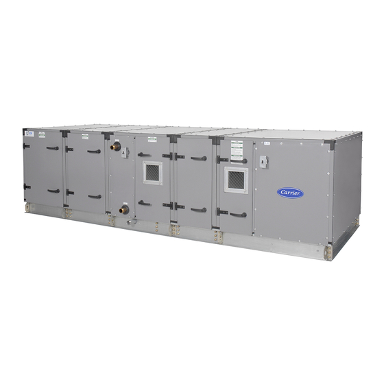
Indoor and weathertight outdoor air handlers
Table of Contents

Advertisement

CONTENTS
INTRODUCTION . . . . . . . . . . . . . . . . . . . . . . . . . . . . . . 3
SAFETY CONSIDERATIONS . . . . . . . . . . . . . . . . . . . 3
PRE-INSTALLATION . . . . . . . . . . . . . . . . . . . . . . . . . 84
Inspection . . . . . . . . . . . . . . . . . . . . . . . . . . . . . . . . . 84
Rigging and Handling . . . . . . . . . . . . . . . . . . . . . . . . 84
Long-Term Storage . . . . . . . . . . . . . . . . . . . . . . . . . . 84
Service Clearance . . . . . . . . . . . . . . . . . . . . . . . . . . . 84
Drain Positioning . . . . . . . . . . . . . . . . . . . . . . . . . . . 84
Unit Suspension . . . . . . . . . . . . . . . . . . . . . . . . . . . . 84
Internal Vibration Isolation . . . . . . . . . . . . . . . . . . . . 85
External Vibration Isolation . . . . . . . . . . . . . . . . . . . 85
Roof Curb . . . . . . . . . . . . . . . . . . . . . . . . . . . . . . . . . . 85
Pier or Beam Mount . . . . . . . . . . . . . . . . . . . . . . . . . 86
INSTALLATION . . . . . . . . . . . . . . . . . . . . . . . . . . . . . 87
Duct Connections . . . . . . . . . . . . . . . . . . . . . . . . . . . 90
Panel Cutting . . . . . . . . . . . . . . . . . . . . . . . . . . . . . . . 97
Face and Bypass Dampers . . . . . . . . . . . . . . . . . . . 97
Zone Damper Section . . . . . . . . . . . . . . . . . . . . . . . 100
Mixing Box Damper Actuators . . . . . . . . . . . . . . . . 104
Vertical Draw-Thru Units . . . . . . . . . . . . . . . . . . . . 104
BOX SECTIONS . . . . . . . . . . . . . . . . . . . . . . . . . . 104
Stacked Units Turning Plenum . . . . . . . . . . . . . . . 104
Fan Sled Disassembly . . . . . . . . . . . . . . . . . . . . . . 106
Manufacturer reserves the right to discontinue, or change at any time, specifications or designs without notice and without incurring obligations.
Catalog No. 04-53390024-01
Installation, Start-Up and
Service Instructions
Printed in U.S.A.
Indoor and Weathertight Outdoor
Fan Sled Dimensions . . . . . . . . . . . . . . . . . . . . . . . .106
Fan Motors and Drives . . . . . . . . . . . . . . . . . . . . . .110
Page
Motor Power Wiring . . . . . . . . . . . . . . . . . . . . . . . . . 110
Sheaves . . . . . . . . . . . . . . . . . . . . . . . . . . . . . . . . . . 110
V-Belts . . . . . . . . . . . . . . . . . . . . . . . . . . . . . . . . . . .111
Direct Drive Fan Alignment . . . . . . . . . . . . . . . . . . .113
Outdoor Hoods and Louvers . . . . . . . . . . . . . . . . .113
(Outdoor Unit - All Sizes) . . . . . . . . . . . . . . . . .114
Humidifier Installation . . . . . . . . . . . . . . . . . . . . . . .121
AND 87)
Assembly of Vertical Manifolds . . . . . . . . . . . . . . .124
Coil Installation . . . . . . . . . . . . . . . . . . . . . . . . . . . .124
Coil Freeze-Up Protection . . . . . . . . . . . . . . . . . . . .129
Distributor Nozzle Change-Out . . . . . . . . . . . . . . . .131
Filter Drier . . . . . . . . . . . . . . . . . . . . . . . . . . . . . . . . .131
TXV (Thermostatic Expansion Valve) . . . . . . . . . .131
Hot Gas Bypass . . . . . . . . . . . . . . . . . . . . . . . . . . . .133
Hot Gas Bypass Piping and Wiring . . . . . . . . . . . .136
Condensate Drain . . . . . . . . . . . . . . . . . . . . . . . . . .137
Form 39M-21SI Rev. B
Pg 1
Aero
39MN,MW03-110
Air Handlers
8-2020
Replaces: 39M-20SI
®

Advertisement

Table of Contents
loading

Summary of Contents for Carrier Aero 39MN Series

  • Page 1: Table Of Contents

    Aero ® 39MN,MW03-110 Indoor and Weathertight Outdoor Air Handlers Installation, Start-Up and Service Instructions CONTENTS Fan Sled Dimensions ......106 Fan Motors and Drives .
  • Page 2 • BLOW-THRU • RIGGING AND STACKING • CAULK/SEALANT APPLICATION Fan Motor Wiring Recommendations ..137 • ERV WHEEL MOTOR WIRING Motor Nameplate Data ..... . . 140 Marine Lights and Convenience Outlets .
  • Page 3: Introduction

    Motor Location ......255 WARNING • INTERNALLY ISOLATED UNIT Lubrication ....... . 255 CHECK for adequate ventilation when welding, cutting, or •...
  • Page 4: Unit And Component Identification

    For further information on unit and component identification con- tact your Carrier representative for the AHUBuilder program. ® Refer to the 39M Product Data catalog for more information on individual component sections.
  • Page 5 000001 ® 39M – Aero Revision Level Air Handler † Code Model Finish and Thermal Option N – Indoor Unit W – Outdoor Unit Order Type S – Special Order Unit Size X – Standard Order Shipping No. of Pieces Example: 12 = 1 of 2 22 = 2 of 2 000001 thru 999999 –...
  • Page 6 28MC V 6 20 F D A 020 A R N – Revision Level 28MC – 1/2 in. Chilled Water 28MH – 1/2 in. Hot Water Coating N – Non-Coated E – E-Coated Coil Position H – Horizontal V – Vertical Hand R –...
  • Page 7 28MZ H 1 26 F B T 074 A X N – – – Coil Revision 28MZ – IDT Steam Coating Coil Position N – Non-Coated H – Horizontal E – E-Coated V – Vertical X – Always Rows 1 – 1 Row 2 –...
  • Page 8 28ME V 4 32 B A A 065 Z R N – 28ME – Direct Expansion Revision Level Coil Position Coating V – Vertical N – Non-Coated E – E-Coated Rows 4 – 4 Row Hand 6 – 6 Row R –...
  • Page 9 – 28MG M 04 G R A H X Casing Length 28MG – Integral Face and Bypass Unit Unit Casing 39M Unit Size Code Size Length (in.) Code Size – 26.0 — – – 36W – – 40W 24.4 — –...
  • Page 10 28MD V 4 30 F A C 092 A R N A A – Always 28MD – 5/8 in. Chilled Water 28MJ – 5/8 in. Hot Water Coating N – Non-Coated E – E-Coated Coil Position H – Horizontal V – Vertical Hand R –...
  • Page 11 – 304 SS HX-Galv. Frame – 21W – 85W – 25W – 96W Fuel Type N – Natural Gas Carrier Gas Heat Code L – Propane 11-35 – Duct Furnaces 36-62, 70 – Rack Furnaces Altitude and Country – 0-2000/USA –...
  • Page 12 93 MR 01 18 B A 02 0 1 0 3 S - Fan Motor Revision Level High Efficiency Fan Application Premium Efficiency Return/Exhaust Supply Horsepower* Supplier Designation 1 1/2 Not Used (Always 0) 7 1/2 Application Mounting F1† F2† Voltage F3** 115/230-1-60...
  • Page 13 70.0 75.0 NOTES: 1. Weights and dimensions are approximate. 54.0 For more exact dimensions, consult with a 82.0 local Carrier Sales Engineer or select the 57.0 desired unit using AHUBuilder ® software. 2. All dimensions in inches, unless otherwise 82.0 noted.
  • Page 14 Air Distribution Components Exhaust Filter mixing Mixing box Mixing box Air mixer Exhaust 7 Internal External face box (side (side inlet) face and and bypass outlet) bypass damper Filtration Sections damper section section FRONT HEPA LOAD FILTER Horizontal Horizontal Horizontal Horizontal Horizontal bag/front loading...
  • Page 15 Table 1 — 39MN,MW Component Weights and Lengths, Sizes 03W to 21W SECTION DIMENSIONS (in.) AND WEIGHTS (lb) Nominal cfm at 1500 3000 3500 4000 4500 5000 5500 6000 6000 7000 8000 8500 9000 10500 500 fpm Unit Size 03W 06W 07T 08W 09T 10W 11T 12W 12T 14W 16T 17W Indoor H (in.) Outdoor H (in.) Indoor W (in.)
  • Page 16 Table 1 — 39MN,MW Component Weights and Lengths, Sizes 03W to 21W (cont) SECTION DIMENSIONS (in.) AND WEIGHTS (lb) Nominal cfm at 1500 3000 3500 4000 4500 5000 5500 6000 6000 7000 8000 8500 9000 10500 500 fpm Unit Size 03W 06W 07T 08W 09T 10W 11T 12W 12T 14W 16T 17W Indoor H (in.) Outdoor H (in.)
  • Page 17 Table 2 — 39MN,MW Component Weights and Lengths, Sizes 22T to 42T SECTION DIMENSIONS (in.) AND WEIGHTS (lb) Nominal cfm at 11000 12500 125000 15000 15000 17500 18000 18500 20000 21000 500 fpm Unit Size Indoor H (in.) Outdoor H (in.) Indoor W (in.) Outdoor W (in.) ITEM...
  • Page 18 Table 2 — 39MN,MW Component Weights and Lengths, Sizes 22T to 42T (cont) SECTION DIMENSIONS (in.) AND WEIGHTS (lb) Nominal cfm at 11000 12500 125000 15000 15000 17500 18000 18500 20000 21000 500 fpm Unit Size Indoor H (in.) Outdoor H (in.) Indoor W (in.) Outdoor W (in.) ITEM...
  • Page 19 Table 3 — 39MN,MW Component Weights and Lengths, Sizes 50W to 110W SECTION DIMENSIONS (in.) AND WEIGHTS (lb) Nominal cfm at 25000 25500 29000 30500 36000 42500 48000 55000 500 fpm Unit Size 110W Indoor H (in.) Outdoor H (in.) Indoor W (in.) 93.5 93.5...
  • Page 20 Table 3 — 39MN,MW Component Weights and Lengths, Sizes 50W to 110W (cont) SECTION DIMENSIONS (in.) AND WEIGHTS (lb) Nominal cfm at 500 25000 25500 29000 30500 36000 42500 48000 55000 Unit Size 110W Indoor H (in.) Outdoor H (in.) Indoor W (in.) 93.5 93.5...
  • Page 21 Table 4 — Direct Drive Plenum Fan Section AWL DT SUP / DT SUP / MOTOR BT SUP / RETURN MOTOR BT SUP / RETURN FAN SIZE EXHAUST FAN SIZE EXHAUST FRAME (in.) FRAME (in.) (in.) (in.) 143T 143T 145T 145T 182T 182T...
  • Page 22 Table 5 — Physical Data — Fan Offerings by Unit Size and Type FORWARD CURVE FANS SUPPLY RETURN / EXHAUST UNIT HP / FRAME HP / FRAME HP / FRAME HP / FRAME SIZE WHEEL WHEEL WHEEL WHEEL A9-4A 5 / 184T 0.5 / 56 A9-4A 5 / 184T...
  • Page 23 Table 5 — Physical Data — Fan Offerings by Unit Size and Type (cont) AIRFOIL FANS SUPPLY RETURN / EXHAUST UNIT HP / FRAME HP / FRAME HP / FRAME HP / FRAME SIZE WHEEL WHEEL WHEEL WHEEL 5 / 184T 0.5 / 56 5 / 184T 0.5 / 56...
  • Page 24 Table 5 — Physical Data — Fan Offerings by Unit Size and Type (cont) DIRECT DRIVE PLENUM FANS SUPPLY/RETURN/EXHAUST HP / FRAME HP / FRAME HP / FRAME UNIT FAN WHEEL WHEEL WHEEL SIZE SIZE C SIZE A SIZE B 5 / 184T 0.5 / 56 5 / 184T...
  • Page 25 Table 6 — Physical Data — Fan Data by Wheel Diameter and Type FORWARD CURVE FANS INLET FAN SHAFT DIAMETER FAN WHEEL WEIGHT WHEEL MAX SPEED (RPM) NUMBER CONE (in.)* (LB) DIAMETER OF FAN K FACTOR WHEEL DIAMETER (in.) BLADES CLASS 1 CLASS 2 CLASS 1...
  • Page 26 Table 6 — Physical Data — Fan Data by Wheel Diameter and Type (cont) BELT DRIVE PLENUM FANS INLET FAN SHAFT DIAMETER FAN WHEEL WEIGHT MAX SPEED (RPM) WHEEL NUMBER CONE (in.)* (lb) DIAMETER OF FAN K FACTOR WHEEL DIAMETER (in.) BLADES (in.)
  • Page 27 MAX ALLOWABLE MAX ALLOWABLE MODEL RADIAL RUNOUT AXIAL RUNOUT (in.) (in.) 0.10 0.10 0.10 0.10 0.10 0.10 0.10 0.10 0.10 0.10 0.15 0.15 0.15 0.15 0.15 0.15 0.15 0.15 0.15 0.15 0.20 0.20 0.20 0.20 0.20 0.20 0.20 0.20 Fig. 14 — Direct Drive Wheel Dimensions BELT DRIVEN PLENUM FAN SINGLE/DUAL DIRECT DRIVE PLENUM FAN WHEEL TO INLET CONE DIMENSIONS (INCHES)
  • Page 28 Table 7 — Coil Data (03W-12W) 39M UNIT SIZE -in. CHILLED WATER/DIRECT EXPANSION Large Face Area Nominal Capacity (cfm) at 500 fpm 1,736 2,951 3,837 3,819 4,531 4,965 5,833 6,380 6,319 Lower Coil Height (in.) 42.5 27.5 45.0 27.5 52.5 52.5 Upper Coil Height (in.) Length (in.)
  • Page 29 Table 7 — Coil Data (03W-12W) (cont) 39M UNIT SIZE Medium Face Area Nominal Capacity (cfm) at 700 fpm 1,458 2,479 4,171 3,500 5,075 4,550 6,533 7,145 6,825 Lower Coil Height (in.) Upper Coil Height (in.) Length (in.) Total Face Area (sq ft) 10.2 Small Face Area Nominal Capacity (cfm) at 700 fpm...
  • Page 30 Table 7 — Coil Data (03W-12W) (cont) 39M UNIT SIZE Small Face Area Nominal Capacity (cfm) at 700 fps — 2,479 2,654 2,917 2,960 3,792 3,733 4,594 3,792 Height (in.) — Length (in.) — Total Face Area (sq ft) — Bypass Face Area (internal) Nominal Capacity (cfm) at 700 fpm 1,458...
  • Page 31 Table 8 — Coil Data (14W-25T) 39M UNIT SIZE -in. CHILLED WATER/DIRECT EXPANSION Large Face Area Nominal Capacity (cfm) at 500 fpm 7,170 7,587 8,464 8,898 10,720 11,016 12,205 12,335 Lower Coil Height (in.) 30.0 37.5 32.5 47.5 35.0 47.5 37.5 Upper Coil Height (in.) 27.5...
  • Page 32 Table 8 — Coil Data (14W-25T) (cont) 39M UNIT SIZE -in. STEAM HEATING Large Face Area Nominal Capacity (cfm) at 700 fpm 9,465 11,083 11,375 12,556 14,219 15,079 16,188 17,150 Lower Coil Height (in.) Upper Coil Height (in.) Length (in.) Total Face Area (sq ft) 13.5 15.8...
  • Page 33 Table 8 — Coil Data (14W-25T) (cont) 39M UNIT SIZE -in. HOT WATER HEATING Large Face Area Nominal Capacity (cfm) at 700 fpm 9,465 11,083 11,375 12,556 14,219 15,079 16,188 17,865 Lower Coil Height (in.) Upper Coil Height (in.) Length (in.) Total Face Area (sq ft) 13.5 15.8...
  • Page 34 Table 8 — Coil Data (14W-25T) (cont) 39M UNIT SIZE -in. Hot Water Integral Face and Bypass Nominal Capacity (cfm) 7,000 7,500 8,500 8,500 10,500 11,000 12,500 12,500 Coil Height (in.) 30.6 65.0 24.0 53.0 33.0 59.0 33.0 64.0 Length (in.) 59.4 26.4 59.4...
  • Page 35 Table 9 — Coil Data (30W-51T) 39M UNIT SIZE -in. CHILLED WATER/DIRECT EXPANSION Large Face Area Nominal Capacity (cfm) at 500 fpm 15,174 14,852 17,448 18,333 18,438 20,000 20,938 25,278 25,313 Lower Coil Height (in.) 47.5 72.5 37.5 Upper Coil Height (in.) 37.5 Length (in.) Total Face Area (sq ft)
  • Page 36 Table 9 — Coil Data (30W-51T) (cont) 39M UNIT SIZE -in. CHILLED WATER Large Face Area Nominal Capacity (cfm) at 500 fpm 14,375 15,365 18,146 18,000 18,438 20,000 20,938 24,917 25,313 Lower Coil Height (in.) Upper Coil Height (in.) Length (in.) Total Face Area (sq ft) 28.8 30.7...
  • Page 37 Table 9 — Coil Data (30W-51T) (cont) 39M UNIT SIZE 1-in. STEAM HEATING Large Face Area Nominal Capacity (cfm) at 700 fpm 20,125 20,650 24,427 25,200 25,813 28,000 29,313 34,883 35,438 Lower Coil Height (in.) Upper Coil Height (in.) Length (in.) Total Face Area (sq ft) 28.8 29.5...
  • Page 38 Table 10 — Coil Data (58T-110W) 39M UNIT SIZE 110W -in. CHILLED WATER/DIRECT EXPANSION Large Face Area Nominal Capacity (cfm) at 500 fpm 28,828 30,694 36,224 42,656 48,125 55,000 Lower Coil Height (in.) 52.5 42.5 Upper Coil Height (in.) 42.5 47.5 47.5 Length (in.)
  • Page 39 Table 10 — Coil Data (58T-110W) (cont) 39M UNIT SIZE 110W -in. CHILLED WATER Large Face Area Nominal Capacity (cfm) at 500 fpm 28,688 30,333 35,667 42,000 47,250 54,000 Lower Coil Height (in.) Upper Coil Height (in.) Length (in.) Total Face Area (sq ft) 57.4 60.7 71.3...
  • Page 40 Table 10 — Coil Data (58T-110W) (cont) 39M UNIT SIZE 110W 1-in. STEAM HEATING Large Face Area Nominal Capacity (cfm) at 700 fpm 40,163 42,467 49,933 58,800 66,150 75,600 Lower Coil Height (in.) Upper Coil Height (in.) Length (in.) Total Face Area (sq ft) 57.4 60.7 71.3...
  • Page 41 Table 11 — Direct-Expansion Circuiting Data Medium Face Area Coils 39M UNIT SIZE CIRCUITING TYPE Quarter Half Quarter Half Full Quarter Half Full Double Quarter Half Full Quarter Half Full Double Quarter Half Full Airflow (cfm) at 500 fpm 1,215 2,066 2,708 2,778...
  • Page 42 Table 11 — Direct-Expansion Circuiting Data (cont) Medium Face Area Coils (cont) 39M UNIT SIZE CIRCUITING TYPE Half Full Double Quarter Half Full Half Full Double Quarter Half Full Half Full Half Full Half Full Airflow (cfm) at 500 fpm 4,444 4,965 4,861...
  • Page 43 Table 11 — Direct-Expansion Circuiting Data (cont) Medium Face Area Coils (cont) 39M UNIT SIZE CIRCUITING TYPE Half Full Double Half Full Double Half Full Double Half Full Double Half Full Double Airflow (cfm) at 500 fpm 9,028 8,976 10,278 9,358 12,778 Total Face Area (sq ft)
  • Page 44 Table 11 — Direct-Expansion Circuiting Data (cont) Medium Face Area Coils (cont) 39M UNIT SIZE CIRCUITING TYPE Half Full Double Half Full Double Full Double Half Full Double Full Double Airflow (cfm) at 500 fpm 11,267 13,958 15,000 15,365 18,333 Total Face Area (sq ft) 22.5 27.9...
  • Page 45 Table 11 — Direct-Expansion Circuiting Data (cont) Medium Face Area Coils (cont) 39M UNIT SIZE CIRCUITING TYPE Half Full Double Full Double Half Full Double Half Full Double Airflow (cfm) at 500 fpm 17,448 19,861 21,094 23,906 Total Face Area (sq ft) 34.9 39.7 42.2...
  • Page 46 Table 11 — Direct-Expansion Circuiting Data (cont) Medium Face Area Coils (cont) 39M UNIT SIZE 110W CIRCUITING TYPE Full Double Full Double Full Double Full Double Full Double Airflow (cfm) at 500 fpm 25,278 29,722 35,000 39,375 45,000 Total Face Area (sq ft) 50.6 59.4 70.0...
  • Page 47 Table 11 — Direct-Expansion Circuiting Data (cont) Large Face Area Coils 39M UNIT SIZE CIRCUITING TYPE Quarter Half Quarter Half Full Quarter Half Full Double Quarter Half Full Quarter Half Full Double Airflow (cfm) at 500 fpm 1,736 2,951 3,837 3,819 4,531 Total Face Area (sq ft)
  • Page 48 Table 11 — Direct-Expansion Circuiting Data (cont) Large Face Area Coils (cont) 39M UNIT SIZE CIRCUITING TYPE Quarter Half Full Quarter Half Full Double Quarter Half Full Quarter Half Full Double Airflow (cfm) at 500 fpm 4,965 5,833 6,319 6,380 Total Face Area (sq ft) 11.7 12.6...
  • Page 49 Table 11 — Direct-Expansion Circuiting Data (cont) Large Face Area Coils (cont) 39M UNIT SIZE CIRCUITING TYPE Quarter Half Full Quarter Half Full Double Half Full Double Airflow (cfm) at 500 fpm 7,170 7,587 8,464 Total Face Area (sq ft) 14.3 15.2 16.9...
  • Page 50 Table 11 — Direct-Expansion Circuiting Data (cont) Large Face Area Coils (cont) 39M UNIT SIZE CIRCUITING TYPE Half Full Double Half Full Double Half Full Double Half Full Double Airflow (cfm) at 500 fpm 8,898 10,720 11,016 12,205 Total Face Area (sq ft) 17.8 21.4 22.0...
  • Page 51 Table 11 — Direct-Expansion Circuiting Data (cont) Large Face Area Coils (cont) 39M UNIT SIZE CIRCUITING TYPE Half Full Double Half Full Double Half Full Double Airflow (cfm) at 500 fpm 12,335 15,174 14,852 Total Face Area (sq ft) 24.7 30.3 29.7 Tubes in Face...
  • Page 52 Table 11 — Direct-Expansion Circuiting Data (cont) Large Face Area Coils (cont) 39M UNIT SIZE CIRCUITING TYPE Half Full Double Full Double Half Full Double Full Double Airflow (cfm) at 500 fpm 17,448 18,438 18,438 20,000 Total Face Area (sq ft) 34.9 36.9 36.9...
  • Page 53 Table 11 — Direct-Expansion Circuiting Data (cont) Large Face Area Coils (cont) 39M UNIT SIZE CIRCUITING TYPE Half Full Double Full Double Quarter Half Full Double Airflow (cfm) at 500 fpm 20,938 25,278 25,313 Total Face Area (sq ft) 41.9 50.6 50.6 Tubes in Face...
  • Page 54 Table 11 — Direct-Expansion Circuiting Data (cont) Large Face Area Coils (cont) 39M UNIT SIZE CIRCUITING TYPE Full Double Full Double Full Double Full Double Airflow (cfm) at 500 fpm 28,828 30,694 35,625 41,892 Total Face Area (sq ft) 57.7 61.4 71.3 83.8...
  • Page 55 Table 11 — Direct-Expansion Circuiting Data (cont) Large Face Area Coils (cont) 39M UNIT SIZE 110W CIRCUITING TYPE Full Double Full Double Airflow (cfm) at 500 fpm 48,125 55,000 Total Face Area (sq ft) 96.3 110.0 Tubes in Face Tube Length (in.) No.
  • Page 56 Table 12 — -in. Water Coil Connection Sizes 39M UNIT SIZE CIRCUIT FACE AREA ROWS TYPE Nozzle Size (in. MPT) 1, 2 HALF/FULL HALF/FULL DOUBLE LARGE HALF 6, 8, 10 FULL DOUBLE (2)2.5 (2)2.5 (2)2.5 (2)3 1, 2 HALF/FULL HALF/FULL DOUBLE MEDIUM HALF...
  • Page 57 Table 13 — -in. Water Coil Connection Sizes (cont) 39M UNIT SIZE CIRCUIT FACE AREA ROWS 110W TYPE Nozzle Size (in. MPT) HALF (2)1.5 (2)1.5 (2)1.5 (2)1.5 (2)1.5 (2)2 (2)2 (2)2 (2)2 (2)2 HALF (2)1.5 (2)1.5 (2)1.5 (2)1.5 (2)1.5 (2)2 (2)2 (2)2 (2)2...
  • Page 58 Table 16 — Hot Water — Integral Face and Bypass Coil Connection Sizes (cont) 39M UNIT SIZE ROWS CONNECTION 110W Nozzle Size (in. MPT) INLET OUTLET INLET OUTLET INLET OUTLET Table 17 — Steam — Integral Face and Bypass Coil Connection Sizes 39M UNIT SIZE ROWS CONNECTION...
  • Page 59 Table 19 — Coil Volume (Gal. Water) (cont) 39M UNIT SIZE 110W HOT WATER Large Face Area 1-Row 2-Row Medium Face Area 1-Row 2-Row Small Face Area 1-Row — 2-Row — Bypass Face Area 1-Row 2-Row Integral Bypass Face Area 1-Row —...
  • Page 60 Table 20 — Dry Coil Weights (lb) 39M UNIT SIZE COIL FACE ROWS TYPE AREA 03W 06W LARGE MEDIUM CHILLED WATER OR DIRECT EXPANSION — SMALL — — BYPASS LARGE MEDIUM HOT WATER — — — SMALL — — — BYPASS LARGE MEDIUM...
  • Page 61 Table 20 — Dry Coil Weights (lb) (cont) 39M UNIT SIZE COIL FACE TYPE AREA 110W LARGE MEDIUM -IN. IDT STEAM — — — SMALL — — — BYPASS — — — INTEGRAL — WATER FACE — — STEAM BYPASS —...
  • Page 62 Table 20 — Dry Coil Weights (lb) (cont) 39M UNIT SIZE FACE COIL TYPE ROWS AREA 110W LARGE MEDIUM HOT WATER — — — — — — — — — — — — SMALL — — — — — — —...
  • Page 63 Table 21 — Motor Weights (lb) 230/460-3-60 200/400-3-50* 575-3-60 TEFC TEFC TEFC 60/68 60/66 65/66 89/99 142/158 154/200 250/259 287/290 394/368 436/436 416† 470† 661/661 403† 527† 686/686 652** 790† 706** 850** 651† 884† 782** 1475** 1133† 1450† 1008† 1000** 1600** 1210†...
  • Page 64 Table 22 — Forward-Curved Fan Drive Centerline Distances in Inches BHF/BHR DBF/DBR THF/THR UBF/UBR FAN SHAFT DIAM. (in.) 39M UNIT FAN MODEL MOTOR SIZE SIZE CLASS 1 CLASS 2 143T FC A9-4A 145T 182T 184T 143T FC A9-4A 145T 182T 184T 10.6 11.6...
  • Page 65 Table 22 — Forward-Curved Fan Drive Centerline Distances in Inches (cont) BHF/BHR DBF/DBR THF/THR UBF/UBR FAN SHAFT DIAM. (in.) 39M UNIT FAN MODEL MOTOR SIZE SIZE CLASS 1 CLASS 2 18.9 21.6 18.9 21.6 17.5 20.4 16.3 19.1 143T 18.9 21.6 18.9 21.6...
  • Page 66 Table 22 — Forward-Curved Fan Drive Centerline Distances in Inches (cont) BHF/BHR DBF/DBR THF/THR UBF/UBR FAN SHAFT DIAM. (in.) 39M UNIT FAN MODEL MOTOR SIZE SIZE CLASS 1 CLASS 2 213T 22.0 23.5 18.0 19.7 19.8 21.5 18.9 20.5 FC A15-15A 215T 22.0 23.5...
  • Page 67 Table 22 — Forward-Curved Fan Drive Centerline Distances in Inches (cont) BHF/BHR DBF/DBR THF/THR UBF/UBR FAN SHAFT DIAM. (in.) 39M UNIT FAN MODEL MOTOR SIZE SIZE CLASS 1 CLASS 2 213T 30.8 33.2 23.7 26.6 27.2 30.0 25.2 27.9 215T 30.8 33.2 23.7...
  • Page 68 Table 22 — Forward-Curved Fan Drive Centerline Distances in Inches (cont) BHF/BHR DBF/DBR THF/THR UBF/UBR FAN SHAFT DIAM. (in.) 39M UNIT FAN MODEL MOTOR SIZE SIZE CLASS 1 CLASS 2 182T 32.6 34.8 24.7 27.4 28.0 30.6 27.0 29.5 184T 32.6 34.8 24.7...
  • Page 69 Table 22 — Forward-Curved Fan Drive Centerline Distances in Inches (cont) BHF/BHR DBF/DBR THF/THR UBF/UBR FAN SHAFT DIAM. (in.) 39M UNIT FAN MODEL MOTOR SIZE SIZE Class 1 Class 2 254T 31.9 34.1 23.2 25.9 26.0 28.5 27.5 29.8 256T 31.9 34.1 23.2...
  • Page 70 Table 22 — Forward-Curved Fan Drive Centerline Distances in Inches (cont) BHF/BHR DBF/DBR THF/THR UBF/UBR FAN SHAFT DIAM. (in.) 39M UNIT FAN MODEL MOTOR SIZE SIZE Class 1 Class 2 256T 34.0 36.3 25.8 28.6 28.5 31.2 29.8 32.2 284T 33.5 35.8 25.5...
  • Page 71 Table 22 — Forward-Curved Fan Drive Centerline Distances in Inches (cont) BHF/BHR DBF/DBR THF/THR UBF/UBR FAN SHAFT DIAM. (in.) 39M UNIT FAN MODEL MOTOR SIZE SIZE Class 1 Class 2 182T 46.1 48.6 27.0 31.9 35.7 39.5 37.6 40.4 184T 46.1 48.6 27.0...
  • Page 72 Table 23 — Airfoil Fan Drive Centerline Distances in Inches FAN SHAFT DIAM. BHF/BHR DBF/DBR THF/THR UBF/UBR FAN MODEL (in.) 39M UNIT SIZE MOTOR SIZE CLASS 1 CLASS 2 16.3 17.6 14.0 15.5 15.0 16.5 14.8 16.2 143T 16.3 17.6 14.0 15.5 15.0...
  • Page 73 Table 23 — Airfoil Fan Drive Centerline Distances in Inches (cont) BHF/BHR DBF/DBR THF/THR UBF/UBR FAN SHAFT DIAM. (in.) 39M UNIT MOTOR MODEL SIZE SIZE CLASS 1 CLASS 2 19.5 20.3 15.0 15.5 17.3 18.2 19.1 19.9 143T 19.5 20.3 15.0 15.5 17.3...
  • Page 74 Table 23 — Airfoil Fan Drive Centerline Distances in Inches (cont) BHF/BHR DBF/DBR THF/THR UBF/UBR FAN SHAFT DIAM. (in.) 39M UNIT MOTOR MODEL SIZE SIZE CLASS 1 CLASS 2 145T 13.8 14.3 10.3 10.9 10.6 12.9 13.5 182T 12.9 13.5 10.2 12.0 12.6...
  • Page 75 Table 23 — Airfoil Fan Drive Centerline Distances in Inches (cont) BHF/BHR DBF/DBR THF/THR UBF/UBR FAN SHAFT DIAM. (in.) MOTOR 39M UNIT MODEL SIZE SIZE CLASS 1 CLASS 2 145T 21.2 22.1 18.3 19.3 17.5 19.0 21.2 22.0 182T 20.4 21.3 17.6 18.6...
  • Page 76 Table 23 — Airfoil Fan Drive Centerline Distances in Inches (cont) BHF/BHR DBF/DBR THF/THR UBF/UBR FAN SHAFT DIAM. (in.) MOTOR 39M UNIT MODEL SIZE SIZE CLASS 1 CLASS 2 33.2 35.2 28.1 30.1 30.9 32.9 30.5 32.5 143T 33.2 35.2 28.1 30.1 30.9...
  • Page 77 Table 23 — Airfoil Fan Drive Centerline Distances in Inches (cont) BHF/BHR DBF/DBR THF/THR UBF/UBR FAN SHAFT DIAM. (in.) MOTOR 39M UNIT MODEL SIZE SIZE CLASS 1 CLASS 2 182T 40.6 42.6 33.6 35.6 36.8 38.8 36.4 38.4 184T 40.6 42.6 33.6 35.6...
  • Page 78 Table 23 — Airfoil Fan Drive Centerline Distances in Inches (cont) BHF/BHR DBF/DBR THF/THR UBF/UBR FAN SHAFT DIAM. (in.) MOTOR 39M UNIT MODEL SIZE SIZE CLASS 1 CLASS 2 182T 42.3 44.2 33.6 35.7 38.5 40.7 36.7 38.5 184T 42.3 44.2 33.6 35.7...
  • Page 79 Table 23 — Airfoil Fan Drive Centerline Distances in Inches (cont) BHF/BHR DBF/DBR THF/THR UBF/UBR FAN SHAFT DIAM. (in.) MOTOR 39M UNIT MODEL SIZE SIZE CLASS 1 CLASS 2 182T 54.9 56.8 43.3 45.6 50.8 52.9 49.2 51.1 184T 54.9 56.8 43.3 45.6...
  • Page 80 Table 23 — Airfoil Fan Drive Centerline Distances in Inches (cont) BHF/BHR DBF/DBR THF/THR UBF/UBR FAN SHAFT DIAM. (in.) MOTOR 39M UNIT MODEL SIZE SIZE CLASS 1 CLASS 2 182T 40.6 43.0 21.9 26.7 31.0 34.6 32.3 34.8 184T 40.6 43.0 21.9 26.7...
  • Page 81 Table 24 — Belt Drive Plenum Fan Drive Centerline Distances in Inches FAN SHAFT FAN SHAFT DIAMETER (in.) MOTOR DIAMETER (in.) UNIT MODEL MOTOR FRAME UNIT MODEL CLASS CLASS SIZE FRAME SIZE CLASS CLASS 145T 32.4 33.8 182T 31.9 33.4 143T 184T 31.9...
  • Page 82 Table 24 — Belt Drive Plenum Fan Drive Centerline Distances in Inches (cont) FAN SHAFT FAN SHAFT DIAMETER (in.) MOTOR DIAMETER (in.) MOTOR UNIT MODEL UNIT MODEL FRAME FRAME SIZE CLASS CLASS CLASS CLASS SIZE 182T 52.0 56.5 182T 38.1 39.6 184T 52.0...
  • Page 83 Table 24 — Belt Drive Plenum Fan Drive Centerline Distances in Inches (cont) FAN SHAFT DIAMETER (in.) MOTOR UNIT MODEL FRAME SIZE CLASS CLASS 182T 48.5 53.2 184T 48.5 53.2 213T 48.2 52.9 215T 48.2 52.9 254T 47.7 52.5 256T 47.7 52.5 PF 44HE...
  • Page 84: Pre-Installation

    Check the packing list to ensure that the correct items coverall; if the unit is stored on the ground, extend the cover have been received and notify your Carrier representative of any underneath the unit. Secure the cover with tiedowns. Do not discrepancy.
  • Page 85: Internal Vibration Isolation

    When field-supplied motors and drives have been installed, adjust the isolator springs as shown in Fig. 18 and described as follows: Loosen the locknut on adjusting stem. Turn the adjusting stem until the specified clearance of -in. is obtained. (Turn clockwise to decrease clearance or counterclockwise to increase clearance.) Tighten the locknut.
  • Page 86: Pier Or Beam Mount

    The 14 in. tall curbs weigh 6 lb per linear foot; 24 in. curbs weigh The return and supply ducts must be supported independently 9 lb per linear foot. from the unit. Do not exert weight or downward force on the unit other than minimal force required to attach ductwork.
  • Page 87: Installation

    Failure to assemble the units according to the procedures set forth below is considered improper installation and abuse and may not only negatively impact the weathertight performance of the unit, but may also negatively affect the Carrier warranty. Indoor and Outdoor Unit Shipping Split (All Sizes) NOTE: The following hardware is included with the unit: 2 per split —...
  • Page 88 Find the Power Plug harness and/or Control Plug harness in its position secured for shipment. (Fig. 26). TYPICAL FRAME SPLIT AT FACTORY ASSEMBLED BASERAIL SPLIT ENSURE MINIMUM 1" CLEARANCE BETWEEN 95CD HARNESS AND HORIZONTAL FRAMES SHIPPING SPLIT KIT 39MX41025802 Fig. 26 — Power Harness in Shipped Position at Horizontal Split Verify that the labels on the power plug connectors (Fig.
  • Page 89 SPLIT SECTION L BRACKET NUT (3/8 in.-16) WASHER (3/8 in.) SCREW SCREW (3/8 in.-16 x 8 in.) SEE DETAIL A DETAIL A SPLIT SECTION INTELLICLAMP DETAIL B CONNECTOR (5/16 in.-18) DETAIL B SCREW 5/16 in.-18 x 2 1/2 SCREW SEE DETAIL C DETAIL C A39-4385 SCREW (1/2 in.-13 x 8 in.)
  • Page 90: Stacked Units

    STACKED UNITS After completing the lower level shipping splits assembly, proceed to the upper level shipping split installation using the provided washers, gasket and self-locking nuts. IMPORTANT: If the top level shipping split arrives separately, do not assemble until you have completed the installation of the Fully tighten all bolts starting from the base rails and moving lower level shipping splits.
  • Page 91 Fig. 34 — Stacked Unit Harness Connection at Vertical Split as Shipped Fig. 35 — Stacked Unit Harness Connection at Vertical Split as Assembled...
  • Page 92 MIXING BOX, EXHAUST BOX, AND EXTERNAL BYSPASS DAMPER DETAILS SIDE DAMPER DETAILS 39M UNIT DETAIL JACKSHAFT 39M UNIT DETAIL JACKSHAFT A (WIDTH) B (HEIGHT) SIZE (SECTIONS) (WIDTH) (HEIGHT) DIAMETER (In.) SIZE (SECTIONS) DIAMETER (In.) 25.75 10.75 38.75 14.00 31.75 20.00 46.75 14.00 34.75...
  • Page 93 5.00 3.00 TOP VIEW 15.00 a39-4304 4.00 O.D. OF FRAME O.D. OF FRAME (NOT INCLUDING FLANGE) (NOT INCLUDING FLANGE) PREMIUM MEASUREMENT DAMPER DAMPER FACE VIEW (BLADES SHOWN OPEN) 7/32" DIA. HOLES at 8" C-C WITH RANDOM START POINT SIZES 03-21 DIMENSIONS (in.) AMS LOW AMS HIGH...
  • Page 94 SIZES 25-61 DIMENSIONS (in.) AMS LOW AMS HIGH 39M UNIT LIMIT LIMIT SIZE (CFM) (CFM) 32.55 21.70 38.00 35.48 34.59 30.27 19.45 3729 22,375 47.25 31.50 20.00 17.48 16.59 44.97 29.25 2,570 17,500 38.85 25.90 38.00 35.48 34.59 36.57 23.65 4,505 27,031 58.05...
  • Page 95: Mixing Box/Inlet Plenum/Discharge Plenum/External Bypass/Return Fan

    15.00 a39-4306 X1 ± .25 SIDE VIEW X2 ±.25 .50 TYP. 4 CORNERS A / 3 A / 3 .25 DIA HOLES A / 3 TYP. 4 CORNERS .50 TYP. 4 CORNERS MEASUREMENT DAMPER B1 D1 .44 TYP. 4 SIDES FACE VIEW (BLADES SHOWN OPEN) B2 D2...
  • Page 96: Housed Fan Discharge Connections (Not Plenum Fans)

    HOUSED FAN DISCHARGE CONNECTIONS (NOT PLE- NUM FANS) A39-4314 Discharge air ducts must be attached directly to the discharge side of the unit. This applies to both indoor and outdoor units. For end or top discharge, apply in. thick by 1 in.
  • Page 97: Bottom Return Fan Connections

    Take care in planning before penetrating any panel with elec- NOT LESS THAN 2-1/2 trical conduit, hydronic piping, sensor pickups or wiring. TIMES FAN DIAMETER Once these are routed through a panel, for all practical pur- poses, it becomes a fixed panel that is not easily removed for service access.
  • Page 98 a39-4334 A39-4334 Fig. 43 — Discharge Fabrication, Draw-Thru Plenum Fans...
  • Page 99 AIRFLOW UNIT HAND SIDE FACE AND BYPASS DAMPER DETAILS DIMENSION (IN.) DIMENSION (IN.) 39M UNIT 39M UNIT SIZE SIZE 26.37 26.37 5.69 79.37 49.37 8.69 39.37 26.37 5.69 65.37 78.26 22.61 32.37 39.26 9.21 97.37 49.37 8.69 47.37 29.37 6.09 73.37 81.26 22.61...
  • Page 100: Zone Damper Section

    Table 26 — Damper Operating Torque (in.-lb) 39M UNIT SIZE COMPONENT Zone Damper Mixing or Exhaust Box Side Mixing or Exhaust Box CD60 / Airflow Measuring 8/16 9/19 10/20 10/21 12/25 14/29 15/31 12/25 21/32 14/34 17/36 17/36 20/42 24/50 20/46 Damper Integral and...
  • Page 101: Mixing Box/Filter Mixing Box Damper Linkage

    LINKAGE ADJUSTMENT Mixing Box/Filter Mixing Box Damper Linkage With the damper actuator unpowered and the damper linkage disconnected, rotate the outdoor-air damper so that it is fully CAUTION closed. Make sure the spring return actuator has completed its stroke (with power disconnected this will be achieved). The It is important to properly link the outdoor-air and return-air return-air damper should be fully open at this point.
  • Page 102 ZONE DAMPER DETAILS DIMENSIONS (in.) QTY OF EXTENSION SHAFT 39M UNIT SIZE QTY OF ZONES KITS 28.50 41.50 28.50 49.50 28.50 62.50 34.50 62.50 34.50 67.50 34.50 74.50 40.50 74.50 40.50 81.50 40.50 99.50 52.50 104.50 52.50 104.50 56.50 112.50 68.50 112.50 FLOW...
  • Page 103 DIRECT COUPLED DIRECT COUPLED ACTUATOR ACTUATOR (SIDE MIXING BOX) (SIDE MIXING BOX) ACTUATOR AND JACKSHAFT ARE REPRESENTATIVE ONLY (TYPICAL) ONE ACTUATOR ONLY WHEN USED ROTATION ROTATION TO OPEN TO OPEN WITH LINKAGE ROTATION TO OPEN FLOW FLOW FLOW LINKAGE LINKAGE ROTATION ROTATION LINKAGE...
  • Page 104: Field Supplied And Installed Actuators

    NOTE: While adjusting linkage, one damper must be fully open and the other fully closed. Top and rear dampers are shipped with both dampers in closed position. Loosen the swivel on the inter- connecting linkage bar and fully open rear damper, leaving top damper closed.
  • Page 105 TORQUE 4-6 FT-LB DETAIL A SEE DETAIL A LOCK NUT OVERLAPPED 1/8 IN. LOCK WASHER FLAT WASHER 2-IN. GASKET STUD FACTORY-INSTALLED AROUND PERIMETER OF FRAME FLUSH TO OUTSIDE EDGE a39-4248 Fig. 50 — Securing Fan and Coil Sections Together SCREW THE BASE RAIL OF THE TOP UNIT TO THE TOP FRAMERAIL OF THE BOTTOM UNIT NOTE: Two turning plenums are needed to make a39-4532...
  • Page 106: Fan Sled Disassembly

    a. Belts and sheaves Fan Sled Disassembly b. Motor In some cases, it may be necessary to remove the fan sled from the unit and break it down into smaller components. See Tables 27-30 c. Fan shaft and Fig. 52 for maximum complete fan sled dimensions and hous- d.
  • Page 107 Table 27 — Airfoil Fan Dimensions (in.) FAN SLED ASSEMBLY UNIT WHEEL SIZES Length Width Height Height Height Height AF 101 03W,06W 34.0 23.5 26.0 25.8 24.8 28.6 28.6 36.0 33.5 26.8 28.1 26.9 AF 121 08W,10W 31.6 07T, 09T 42.0 27.8 27.5...
  • Page 108 Table 27 — Airfoil Fan Dimensions (in.) (cont) FAN SLED ASSEMBLY UNIT WHEEL SIZES Length Width Height Height Height Height 59.5 — 78.6 108.5 71.7 72.2 65.5 64.4 93.6 AF 331 95.3 64.9 72.8 73.3 69.9 68.8 97.3 65.5 108.5 78.7 79.5 —...
  • Page 109 Table 28 — Forward Curve Fan Dimensions (in.) (cont) FAN SLED ASSEMBLY WHEEL UNIT SIZES Length Width Height Height Height Height 52.5 79.0 45.7 47.7 38.9 51.6 A20-15A 25T (THF, BHF) 51.6 32.6 45.6 47.6 38.8 40.3 25T (DB, UB) 58.2 40.5 72.0...
  • Page 110: Fan Motors And Drives

    Sheaves 12W,14W,16T,17W, 36.3 34.6 32.0 Factory-supplied drives are pre-aligned and tensioned. However, 14W,16T,17W,18T, Carrier recommends checking the belt tension and alignment be- 37.8 37.4 34.9 21W,22T,25T fore starting the unit. Always check the drive alignment after ad- 17W,21W,22T,25W, justing belt tension.
  • Page 111: Alignment

    See Fig. 55. Adjustable pitch drives are installed on the Tighten belts by turning motor-adjusting jackscrews. Turn motor shaft. Carrier recommends that adjustable sheaves each jackscrew an equal number of turns. should only be used for initial balancing and should be...
  • Page 112 Equalize belt slack so that it is on the same side of belt for all belts. Failure to do so may result in uneven belt stretching. Tension new drives at the deflection force recommended (Table 31). On current production, the correct tension information is listed on the fan drive label.
  • Page 113: Tension Measurement Procedure

    ENTIRE PERIPHERY hours of drive service. INTAKE HOOD Direct Drive Fan Alignment Direct drive fans are aligned in the factory. However, Carrier rec- ommends checking alignment before starting the unit. A39- Ensure the radial distance between fan wheel and inlet cone 2347ef appears visually equal in all directions.
  • Page 114: Coil Connection Housing

    GASKET 0.125 THICK x 1.25 WIDE LOUVER ASSEMBLY INSERT HOOKS THROUGH HOLES TO LIFT LOUVER ASSEMBLY INTO PLACE SCREW 1/4-14 x 3/4 SNS a39-4234 NOTE: All dimensions in inches unless otherwise noted. Fig. 58 — Intake Louver ASSEMBLY SHIPPING POSITION SCREW HOOD GUTTER...
  • Page 115 COIL CONNECTION HOUSING LEGEND CCH — Coil Connection Housing CCH INSTALLATION COMPONENTS NOTE: Shown as single section component for reference. Housing may bridge across 2 or more section components, increasing skid a39-4161 length requirements. Fig. 60 — Coil Connection Housing COIL CONNECTION HOUSING SHIPPING BRACKETS...
  • Page 116 Install the side flashing to the unit by inserting the in. — 14 x in. screws (provided) into the pre-drilled holes in the unit frames. The bottom end of the flashing must be flush with the base rail tab and the upper end of the flashing must be underneath the roof rail as shown in Fig.
  • Page 117 Remove the unit lifting lugs under the coil section that match the CCH side walls. DO NOT REMOVE THE LIFTING LUG BOLTS AS THEY WILL BE USED TO ATTACH THE ANGLE. If the CCH has no door, remove the side panels before pro- ceeding with the installation.
  • Page 118: Power Exhaust Hood Field Installation

    Fig. 75 — Power Exhaust Damper Kit Fig. 73. Remove the steel strapping and remove the boxes Inspect box contents for missing or damaged parts. If any from the return fan section. parts are damaged or missing, contact your Carrier represen- tative for assistance.
  • Page 119 Install gasket flush to each panel flange (top, bottom and sides) as shown below. See Fig. 76. 99SR12022001 99SR12022001 Fig. 78 — Attaching the Side Panels and Bottom Panel After attaching bottom panel to unit, attach bottom panel to side panel using the in.-14 x in.
  • Page 120 99SR12022001 Fig. 81 — Attaching the Angle Brackets 11. Install damper (if ordered) as shown in the Fig. 82. Orient damper blades to open out (in the direction of exhaust air.) Attach the 3 outer angle brackets to secure the damper to the exhaust hood using the in.-14 x in.
  • Page 121: Humidifier Installation

    14. Attach front panel to power exhaust assembly using the in.-14 x in. long sheet metal screws (without neoprene washer.) Also, attach the lifting brackets to each side of the top of the assembly using the in.-14 x in. long sheet metal screws (without neoprene washer.) See Fig.
  • Page 122 CAREL PART NUMBER DESCRIPTION COMPONENTS SAKV000AU0 -in. valve size Cv=0.4 SAKV000BU0 -in. valve size Cv=0.63 -in. MPT x 3-in. nipples SAKV000CU0 -in. valve sizes Cv=1 -in. FPT x 1-in. MPT hex bushings SAKV000DU0 -in. valve sizes Cv=1.6 1-in. union SAKV000EU0 -in.
  • Page 123: Assemble Strainer And Trap Assembly And Valve Assembly (Fig. 88-91)

    ASSEMBLE STRAINER AND TRAP ASSEMBLY AND VALVE ASSEMBLY (FIG. 88-91) Strainer and trap assemblies are sold as separate items through your local Carel representative (shipped unassembled). Figures 88-91 each show a detailed list of components in those kits. Table 32 lists Carel’s available inlet trap strainer kits. Alternatively, strainers and traps from any manufacturer may be used with the Carel humidifier.
  • Page 124: Assembly Of Vertical Manifolds

    a39-4413 NOTE: Bottom feed humidifier shown with field-supplied and installed control valve. Sizes 03-14 are bottom fed. Sizes 17-61 are top feed. Fig. 91 — Control Valve, Strainer and Trap Connected to Supply and Manifold of Humidifier Coil Installation Assembly of Vertical Manifolds NOTE: If installing a replacement coil, refer to Coil Removal sec- The vertical distribution manifolds are inserted into the bottom tion on page 209 for instructions on removing existing coil.
  • Page 125: Installation Of Stacked Coils

    IMPORTANT: The lengths of the coil supports and of the lower coil casings (see Fig. 86). intermediate pans and channels are designed to work with Carrier coils. Substitution of other manufacturer’s coils may CAUTION require that custom mounting components be field fabricated.
  • Page 126 Fig. 93 — Single Slope Condensate Drain — Apply Gasket BAFFLE, TOP CHANNEL, HAT COIL FRAMES BAFFLE, LEFT CHANNEL, HAT BAFFLE, RIGHT ANGLE ATTACHED TO COILS BOTH SIDES IMPORTANT: ADHESIVE GASKET MUST BE PAN, CONDENSATE APPLIED TO THE FULL LENGTH OF THE BOTTOM CENTERED WITHIN SECTION BAFFLE MATING FLANGE TO CREATE SEAL BETWEEN THE COIL SIDE CASING AND THE BAFFLE.
  • Page 127: Water And Steam Coil Piping Recommendations

    See Fig. 97. CHANNEL, HAT TO COIL CASING Piping practices are outlined in the Carrier System Design Manu- al, Part 3, Piping Design. WATER COILS Typically, coils are piped by connecting the supply at the bottom and the return at the top.
  • Page 128: Steam Coils

    STEAM COILS • Drain condensate out of coils completely at the end of the heating season to prevent the formation of acid. Position the steam supply connection at the top of the coil, and the return (condensate) connection at the bottom. The coil tubes must incline downwards toward the return header connection for con- densate drainage.
  • Page 129: Coil Freeze-Up Protection

    INNER DISTRIBUTING TUBE STEAM COILS Fig. 101 — Multiple Coil Low Pressure The inner distributing tube (IDT) steam coil used in the Carrier Piping Gravity Return 39M air-handling units has an inner tube pierced to facilitate the...
  • Page 130: Refrigerant Piping, Direct-Expansion Coils

    Note: The IDT coils must be installed with the tubes draining To minimize the possibility of flooded starts and compressor dam- toward the header end of the coil. Carrier’s IDT steam coils are age during prolonged light load operation, an accumulator can be pitched toward the header end as installed in the unit.
  • Page 131: Distributor Nozzle Change-Out

    best performance; replacement nozzles must be field-installed. The correct nozzle is typically factory-installed. UNIT COIL CASING CASING CAUTION Do not overheat distributor or cap. Failure to comply could result in equipment damage. SOLENOID SIGHT VALVE GLASS UPPER FILTER Perform nozzle change-out procedure as follows: SENSING DRIER SPLIT...
  • Page 132: Solder Techniques

    TXV bulb. Tests have confirmed that this, in addi- tion to the vertical riser bulb location, results in significantly better superheat control over a broader load range. Figures provided in the Carrier Refrigerant Reference Manual il- lustrate these recommendations for various coil splits and com- pressor configurations.
  • Page 133: External Equalizer Connection

    HORIZONTAL MOUNTING VERTICAL MOUNTING (Preferred Method) HEADER SIZE EACH SECTION FOR 80 EQUIVALENT FT. COIL SIZE DOWN EXTERNAL EQUALIZER MIN 15 DIAMETER LINE 2 ELBOWS RETURN CONNECTION DROP BELOW BULB MOUNTING TXV BULB (SEE DETAIL A) MIN 10 DIAMETER DETAIL A MIN 8 DIAMETER REMOTE BULB ON SMALL SUCTION LINE (LESS THAN 7/8 IN.)
  • Page 134 4. If required, install field-supplied adapter bushing or cou- pling to connector inlet before soldering to expansion valve outlet. Table 33 — Auxiliary Side Connector (Hot Gas Bypass) Data CONNECTION SIZES (IN.) SPORLAN CARRIER USED WITH SPORLAN NOZZLE TYPE PART NO. DISTRIBUTOR TYPE SIZE INLET —...
  • Page 135: Special Piping With 4 Splits Per Coil

    SPECIAL PIPING WITH 4 SPLITS PER COIL Manifolding for 2-Face Splits — Refer to Fig. 110 for coils with less than 34 tubes in face. Externally manifold as follows: Manifolding for 2-Face Splits — Refer to Fig. 110 and external- 1.
  • Page 136: Hot Gas Bypass Piping And Wiring

    3. Sweat the pilot solenoid valve supplied in the hot gas Hot Gas Bypass Piping and Wiring accessory package directly to the hot gas bypass valve on INSTALL PIPING (See Fig. 112) -in. ODF external equalizer port. 4. Install field-supplied -in.
  • Page 137: Condensate Drain

    LEGEND ASC — Auxiliary Side Connector TXV — Thermostatic Expansion Valve Refrigerant Check Valve a39-4439 Fig. 112 — Hot Gas Bypass Piping DRAW-THRU Condensate Drain Install a condensate-trapping drain line at the unit’s drain connec- Trap against all upstream static pressure including the drain pan tion;...
  • Page 138 a39-4178 PLENUM MIXING ENSURE ADEQUATE P + 1/2” HEIGHT/CLEARANCE 1/2” Static Pressure Between the Fan Static Pressure Between the Fan MINIMUM FOR DRAIN TO FLOOR and Drain and Drain (Coil and Plenum Section) (Coil and Plenum Section) Fig. 114 — Condensate Drain, Blow-Thru Trapping 1.2 in.
  • Page 139 Table 35 — Electrical Data — Premium Efficiency EISA Compliant Motors ODP/OPSB T-FRAME MOTORS - 1800 RPM ODP/OPSB T-FRAME MOTORS - 3600 RPM FLA FOR 3-PHASE, 60 Hz FLA FOR 3-PHASE, 60 Hz MOTOR EFF. NEMA MOTOR EFF. NEMA VOLTAGES VOLTAGES FRAME FRAME...
  • Page 140: Motor Nameplate Data

    Table 36 — Electrical Data — Premium Efficiency EISA Compliant Motors (cont) ODP/OPSB T-FRAME MOTORS - 1200 RPM TEFC T-FRAME MOTORS - 1200 RPM FLA FOR 3-PHASE, 60 HZ FLA FOR 3-PHASE, 60 HZ MOTOR EFF. NEMA MOTOR EFF. NEMA VOLTAGES VOLTAGES FRAME...
  • Page 141: Fan Motor Starter

    3. Close and secure the fan access door or panel and the Fan Motor Starter starter door cover. When starter is factory-installed, it is wired to the motor and fully 4. Apply power to the starter. tested before shipping. Before proceeding, open the starter cover and fan section access door to check for any damage.
  • Page 142: Start-Up And Test

    2. Remove the appropriate size knockout using a suitable 8. Select MENU to enter the main menu. knockout punch tool. Do NOT use a drill; metal shavings 9. Select CHANGED PAR with the UP/DOWN buttons and will damage the drive. select ENTER.
  • Page 143 Table 37 — VFD Data PROGRAMMED SETTINGS ABB PART MAX. CONTINUOUS MCCB FUSE AMPS OVERLOAD TRIP AMPS MAX. OUTPUT AMPS MOTOR HP NO. ACH550-UH- OUTPUT AMPS RATED AMPS 4 POLE / 2 POLE 4 POLE / 2 POLE 208-230 VOLT / 3 PHASE / 60 HZ (PROGRAMMED TO OPERATE AT 208 VOLTS) 04A6-2 1.8/ 3.0/...
  • Page 144 Table 38 — Air Handler VFD Factory-Set Parameters GROUP PARAMETER VFD DRIVE ONLY VFD WITH E-CLIPSE DESCRIPTION / DESCRIPTION NUMBER NUMBER PARAMETERS PARAMETER 9902 Application Macro Supply Fan Eclipse HVAC / 9902 9904 Motor Control Mode Scalar Scalar 9905 Motor Normal Voltage 9906 Motor Normal Current †...
  • Page 145 Table 38 — Air Handler VFD Factory-Set Parameters (cont) GROUP PARAMETER VFD DRIVE ONLY VFD WITH E-CLIPSE DESCRIPTION / DESCRIPTION NUMBER NUMBER PARAMETERS PARAMETER 3101 Number of Retries 3102 Trial Time 600 sec. 600 sec. 3103 Delay Time 5 sec. 5 sec.
  • Page 146 NOTES: 1. All conductors are no. 22 AWG (American Wire Gage) minimum. 2. Install jumpers if fire/smoke detector, low limit thermostat, or high pressure switch are not required. Fig. 118 — Field-Supplied Control Wiring for VFD Speed Control From a Field Supplied 4 Wire Static Pressure Transducer AI-2 Cable Shield Ground * 0-10 v dc...
  • Page 147 NOTES: 1. All conductors are no. 22 AWG (American Wire Gage) minimum. 2. Install jumpers if fire/smoke detector, low limit thermostat, or high pressure switch are not required. 3. Program desired speed set point in Hz using parameter 1202. Fig. 120 — Field Wiring for High Inertia/Low Horsepower Applications Using VFD as a Starter J1 –...
  • Page 148: Wiring

    WIRING NOTE: Bypasses with a 115-v control transformer can be field modified to incorporate a normally closed safety contact. This 1. Select a suitable location in the bottom panel of the by- safety contact (in addition to the VFD shutdown wiring) wires into pass box to connect field-supplied power source.
  • Page 149: Shunt Trip Installation, Aci Part No. 135046

    TERMINAL STRIP A39-4180 LEGEND MMS — Manual Motor Starter INSTALL ACI SHUNT TRIP Factory Wiring P/N 135046 INTO MMS Field Wiring NOTES: 1. Connect field-supplied 120-vac control signal (from fire/life safety circuit) to 2 leads from shunt trip (P/N 135046). 2.
  • Page 150: Shunt Trip Installation, Aci Part No. 135728 Or

    a39-4502 a39-4503 Fig. 125 — Installing the Shunt Trip (ACI Part No. 135046) a39-4504 a39-4505 a39-4506 Fig. 126 — Running the Leads and Replacing the Cover Shunt Trip Installation, ACI Part No. 135728 or 135728A WARNING Follow these steps to incorporate a 24-v shunt trip (ACI part no. Electrical shock can cause personal injury and death.
  • Page 151 3. Remove the left DIN rail stop, then push the MMS carefully NOTE: For some units, the wire bundle may need to be ad- towards the bottom and lift it off the rail. justed to allow the MMS and the shunt trip device to connect to the DIN rail.
  • Page 152: Vfd Configuration

    a39-4508 a39-4512 SHUNT TRIP Fig. 130 — MMS Before and After Shunt Trip Installation VFD Configuration 4. The Start-Up Assistant will display the parameters that need to be configured. Select the desired values and press The VFD keypad is shown in Fig. 131. The function of SOFT SAVE (SOFT KEY 2) after every change.
  • Page 153: Standard Display Mode

    A stationary arrow indicates that the drive is stopped. For Carrier air handler units, the rotation is al- 4. Press EXIT (SOFT KEY1) to exit the Changed Parame- ways forward.
  • Page 154: Download All Parameters

    DOWNLOAD ALL PARAMETERS To configure the I/O settings, perform the following procedure: 1. Select MENU (SOFT KEY 2). The Main menu will be To download all parameters from the control panel to the VFD, displayed. perform the following procedure: 2. Use the UP or DOWN keys to highlight I/O SETTINGS 1.
  • Page 155: Smoke Control Mode

    system is forced to bypass and runs the motor. The Motor Run BACK-LIT LED flashes green when the system is in override. While in Smoke READY INDICATION LCD DISPLAY (DISPLAY ILLUMINATED) Control, the system only responds to certain inputs. Normally, DOWN when the Smoke Control input contact is switched from closed to BYPASS CONTROL...
  • Page 156: Electric Heaters

    The complete list of programmable relay output functions follows: 8. The heater has lifting hook openings on each end. When the heater is within 3 in. of its final position, reinstall the 0 = NOT SEL 14 = BYPASS OFF crossrail with the box-seal facing down and the panel seal 1 = SYS READY 15 = BYPASS AUTO...
  • Page 157 type cutout. It is wired into the control circuit which operates the Table 39 — Field Wiring for Incoming Conductors magnetic disconnecting contactors (the same contactors that also Sized for 125% of Heater Load switch on and off the various steps of the coil). The secondary manual reset cutout is a bi-metal disk-type cutout.
  • Page 158 LEGEND a39-4380 — Normally Closed NEC — National Electrical Code — Normally Open SCR — Silicon Control Rectifier NOTE: All wiring must be copper and must conform to NEC. Fig. 138 — Full SCR Electric Heat Control...
  • Page 159 LEGEND — Normally Closed a39-4381 NEC — National Electrical Code — Normally Open SCR — Silicon Control Rectifier NOTE: All wiring must be copper and must conform to NEC. Fig. 139 — Vernier SCR Electric Heat Control...
  • Page 160 Table 40 — Electric Heater Data LOW kW EH HIGH kW EH CONTROL CONTROL UNIT FACE TEMP RISE TEMP RISE AIRFLOW kW / SUB CIRCUITS CIRCUITS kW / SUB CIRCUITS CIRCUITS SIZE AREA AT 100% AT 100% SQ FT AMPS AT MAX AMPS AT MAX kW SQ FT...
  • Page 161 Table 40 — Electric Heater Data (cont) LOW kW EH HIGH kW EH CONTROL CONTROL UNIT FACE TEMP RISE TEMP RISE AIRFLOW kW / SUB CIRCUITS CIRCUITS kW / SUB CIRCUITS CIRCUITS SIZE AREA AT 100% AT 100% SQ FT AMPS AT MAX AMPS AT MAX kW...
  • Page 162 Table 40 — Electric Heater Data (cont) LOW kW EH HIGH kW EH CONTROL CONTROL UNIT FACE TEMP RISE TEMP RISE AIRFLOW kW / SUB CIRCUITS CIRCUITS kW / SUB CIRCUITS CIRCUITS SIZE AREA AT 100% AT 100% SQ FT AMPS AT MAX AMPS AT MAX kW...
  • Page 163 Table 40 — Electric Heater Data (cont) LOW kW EH HIGH kW EH CONTROL CONTROL UNIT FACE TEMP RISE TEMP RISE AIRFLOW kW / SUB CIRCUITS CIRCUITS kW / SUB CIRCUITS CIRCUITS SIZE AREA AT 100% AT 100% SQ FT AMPS AT MAX AMPS AT MAX kW...
  • Page 164 Table 40 — Electric Heater Data (cont) LOW kW EH HIGH kW EH CONTROL CONTROL UNIT FACE TEMP RISE TEMP RISE AIRFLOW kW / SUB CIRCUITS CIRCUITS kW / SUB CIRCUITS CIRCUITS SIZE AREA AT 100% AT 100% SQ FT AMPS AT MAX AMPS AT MAX kW...
  • Page 165 Table 40 — Electric Heater Data (cont) LOW kW EH HIGH kW EH CONTROL CONTROL UNIT FACE TEMP RISE TEMP RISE AIRFLOW kW / SUB CIRCUITS CIRCUITS kW / SUB CIRCUITS CIRCUITS SIZE AREA AT 100% AT 100% SQ FT AMPS AT MAX AMPS AT MAX kW...
  • Page 166 Table 40 — Electric Heater Data (cont) LOW kW EH HIGH kW EH CONTROL CONTROL UNIT FACE TEMP RISE TEMP RISE AIRFLOW kW / SUB CIRCUITS CIRCUITS kW / SUB CIRCUITS CIRCUITS SIZE AREA AT 100% AT 100% SQ FT AMPS AT MAX AMPS AT MAX kW...
  • Page 167 Table 40 — Electric Heater Data (cont) LOW kW EH HIGH kW EH CONTROL CONTROL UNIT FACE TEMP RISE TEMP RISE AIRFLOW kW / SUB CIRCUITS CIRCUITS kW / SUB CIRCUITS CIRCUITS SIZE AREA AT 100% AT 100% SQ FT AMPS AT MAX AMPS AT MAX kW...
  • Page 168 Table 40 — Electric Heater Data (cont) LOW kW EH HIGH kW EH CONTROL CONTROL UNIT FACE TEMP RISE TEMP RISE AIRFLOW kW / SUB CIRCUITS CIRCUITS kW / SUB CIRCUITS CIRCUITS SIZE AREA AT 100% AT 100% SQ FT AMPS AT MAX AMPS AT MAX kW...
  • Page 169 Table 40 — Electric Heater Data (cont) LOW kW EH HIGH kW EH CONTROL CONTROL UNIT FACE TEMP RISE TEMP RISE AIRFLOW kW / SUB CIRCUITS CIRCUITS kW / SUB CIRCUITS CIRCUITS SIZE AREA AT 100% AT 100% SQ FT AMPS AT MAX AMPS AT MAX kW...
  • Page 170 Table 40 — Electric Heater Data (cont) LOW kW EH HIGH kW EH CONTROL CONTROL UNIT FACE TEMP RISE TEMP RISE AIRFLOW kW / SUB CIRCUITS CIRCUITS kW / SUB CIRCUITS CIRCUITS SIZE AREA AT 100% AT 100% SQ FT AMPS AT MAX AMPS AT MAX kW...
  • Page 171 Table 40 — Electric Heater Data (cont) LOW kW EH HIGH kW EH CONTROL CONTROL UNIT FACE TEMP RISE TEMP RISE AIRFLOW kW / SUB CIRCUITS CIRCUITS kW / SUB CIRCUITS CIRCUITS SIZE AREA AT 100% AT 100% SQ FT AMPS AT MAX AMPS AT MAX kW...
  • Page 172 Table 40 — Electric Heater Data (cont) LOW kW EH HIGH kW EH CONTROL CONTROL UNIT FACE TEMP RISE TEMP RISE AIRFLOW kW / SUB CIRCUITS CIRCUITS kW / SUB CIRCUITS CIRCUITS SIZE AREA AT 100% AT 100% SQ FT AMPS AT MAX AMPS AT MAX kW...
  • Page 173 Table 40 — Electric Heater Data (cont) LOW kW EH HIGH kW EH CONTROL CONTROL UNIT FACE TEMP RISE TEMP RISE AIRFLOW kW / SUB CIRCUITS CIRCUITS kW / SUB CIRCUITS CIRCUITS SIZE AREA AT 100% AT 100% SQ FT AMPS AT MAX AMPS AT MAX kW...
  • Page 174 Table 40 — Electric Heater Data (cont) LOW kW EH HIGH kW EH CONTROL CONTROL UNIT FACE TEMP RISE TEMP RISE AIRFLOW kW / SUB CIRCUITS CIRCUITS kW / SUB CIRCUITS CIRCUITS SIZE AREA AT 100% AT 100% SQ FT AMPS AT MAX AMPS AT MAX kW...
  • Page 175 Table 40 — Electric Heater Data (cont) LOW kW EH HIGH kW EH CONTROL CONTROL UNIT FACE TEMP RISE TEMP RISE AIRFLOW kW / SUB CIRCUITS CIRCUITS kW / SUB CIRCUITS CIRCUITS SIZE AREA AT 100% AT 100% SQ FT AMPS AT MAX AMPS AT MAX kW...
  • Page 176 Table 40 — Electric Heater Data (cont) LOW kW EH HIGH kW EH CONTROL CONTROL UNIT FACE TEMP RISE TEMP RISE AIRFLOW kW / SUB CIRCUITS CIRCUITS kW / SUB CIRCUITS CIRCUITS SIZE AREA AT 100% AT 100% SQ FT AMPS AT MAX AMPS AT MAX kW...
  • Page 177 Table 40 — Electric Heater Data (cont) LOW kW EH HIGH kW EH CONTROL CONTROL UNIT FACE TEMP RISE TEMP RISE AIRFLOW kW / SUB CIRCUITS CIRCUITS kW / SUB CIRCUITS CIRCUITS SIZE AREA AT 100% AT 100% SQ FT AMPS AT MAX AMPS AT MAX kW...
  • Page 178 Table 40 — Electric Heater Data (cont) LOW kW EH HIGH kW EH CONTROL CONTROL UNIT FACE TEMP RISE TEMP RISE AIRFLOW kW / SUB CIRCUITS CIRCUITS kW / SUB CIRCUITS CIRCUITS SIZE AREA AT 100% AT 100% SQ FT AMPS AT MAX AMPS AT MAX kW...
  • Page 179 Table 40 — Electric Heater Data (cont) LOW kW EH HIGH kW EH CONTROL CONTROL UNIT FACE TEMP RISE TEMP RISE AIRFLOW kW / SUB CIRCUITS CIRCUITS kW / SUB CIRCUITS CIRCUITS SIZE AREA AT 100% AT 100% SQ FT AMPS AT MAX AMPS AT MAX kW...
  • Page 180: Gas Furnace Identification

    (up to 10 racks total). Duct furnaces are IMPORTANT: This furnace is not listed or suitable for Carrier Gas Heat Codes 11-35. Rack furnaces are Carrier Gas drying or process applications. Use in such applications Heat Codes 36-62, and 70. Refer to Fig. 10.
  • Page 181: Condensate Drains

    Check the furnace section for this information, or contact your Carrier service representative. Do not use copper tubing for condensate drain lines. Flue gas condensate is slightly acidic and may corrode lines.
  • Page 182: Venting

    combustion air are not available to the heater, poor combustion • Air from inside building — openings 1 sq in. free area per and inefficient operation will result. 1000 Btuh, but never less than 100 sq in. • Air from outside through a duct — openings 1 sq in. free For outdoor installations, the heating unit cabinet combustion air area per 2000 Btuh openings should be sized to provide 1 sq in.
  • Page 183 Venting for Outdoor Installations — The venting system is INPUT RATING VENT PIPE designed for direct discharge of flue gases to the outdoors. The INPUT RATING (W) (BTUH) DIAMETER vent discharge opening should be located to provide an unob- 75,000 - 149,999 21,980 - 43,958 5 in.
  • Page 184: Gas Supply, Piping, And Connections

    LISTED VENT TERMINAL USE INSULATED VENT OUTDOORS THIMBLE 5 FT. MIN. ROOF (1.52 M) 2 FT. MIN. 1/4 IN. (6 mm) PITCH PER (0.61 M) 1 FT. (305 mm) HORIZONTAL a39-4396 SEE VENT PIPE CONDENSATE DIAMETER TABLE FOR TOTAL VERTICAL DRAIN VENT DIAMETER FLUE HEIGHT...
  • Page 185 manual shut-off valve tapping (see Fig. 149) or the inlet side of the gas valve (Fig. 150-152). For multiple heater installations, IMPORTANT: Gas pressure to appliance controls must never measure inlet pressure to each heater serviced by a single regulator exceed 13.5 in.
  • Page 186 GAS SUPPLY LINE GROUND JOINT MANUAL GAS UNION WITH SHUT-OFF VALVE BRASS SEAT GAS SUPPLY LINE TO CONTROLS PLUGGED 3 IN. 1/8 IN. NPT TEST MIN. GAGE CONNECTION SEDIMENT TRAP Fig. 149 — Sediment Trap, Shut-Off Valve, and Union SECOND STAGE (HI FIRE) MANIFOLD PRESSURE ADJUSTMENT (3/32 IN.
  • Page 187: Gas-Fired Rack System Furnaces

    This documentation is located in the heater section, or contact your Carrier service representative. Fig. 153 — Gas-Fired Rack System Furnace Typical Wiring Diagram...
  • Page 188: Combustion Air Supply

    Fig. 154 — Gas-Fired Rack Furnace Components The furnace module is equipped with manual reset rollout COMBUSTION AIR SUPPLY switch(es) in the event of burner flame rollout. The switch will All gas-fired furnaces need an ample supply of air for proper and open on temperature rise and shut off gas supply through the igni- safe combustion of the fuel gas.
  • Page 189: Gas Supply, Piping, And Connections

    Clearance Requirements for Outdoor Installations connected to each heater serviced by a single regulator so that gas pressure at each heater can be measured with all heaters in Observe the following additional requirements for outdoor operation. installations: • Provide at least 6 feet clearance to side of the unit, where IMPORTANT: When pressure testing at psig or less, close the combustion air inlet or vent (flue) gas discharge is lo-...
  • Page 190: Energy Recovery Ventilation (Erv) Sections

    vent pipe requires custom adapters to ensure leak-free joints. Con- Horizontal Vent System Installation tact a venting system manufacturer for availability, if the venting For all indoor rack system horizontal vent installations, note the system was not included with the heating system. following for proper installation: •...
  • Page 191 LOCK NUT NYLON WASHER WASHER SEALING WASHER USE 0.75 x 1.125 FRAME GASKET PLACE AROUND PERIMETER OF FRAME FLUSH TO OUTSIDE EDGE VERIFY FACTORY APPLICATION OF WIDE GASKET HAS RIGHT OF WAY SEALANT/CAULKING (ALL 4 CORNERS) APPLY (4) 2" (2.00 X 0.75) PCS OF 93M6X70500X000002 TO INSIDE CORNERS PUSH EDGE OF GASKET...
  • Page 192: Rigging And Stacking

    93M6X70500X000002, (¾" x 2" GASKET) SHALL BE INSTALLED ON THE OUTLET FRAME/BASERAIL LOOPS OF THE FOLLOWING SECTIONS: GASKET OVERLAPPED AND PLACED LAST SECTION OF OUTDOOR AIR MODULE OVER BASERAILS AND FRAME JOIN LAST SECTION OF EXHAUST AIR MODULE OUTLET SIDE ONLY ERV MODULE Y1/Y2/Y3 GASKET APPLIED TO OUTLET SIDE OF OUTDOOR UNIT SPLIT ONLY...
  • Page 193: Caulk/Sealant Application

    Stack the ERV wheel section and secure baserail to lower sec- tion as shown in Fig. 163. Take care to vertically align the faces of the stacked vertical frames. Secure the ERV wheel section 3 in. baserail to the return air module frame intelliclamp as shown in Fig.
  • Page 194: Erv Wheel Motor Wiring

    Fig. 167 — Secure ERV Wheel on 6 in. Baserail VERIFY FACTORY APPLICATION OF SEALANT/CAULKING OUTDOOR UNITS ONLY - FIELD INSTALLER SHALL APPLY SEALANT/ CAULK TO ALL SIMILIAR FRAME TO FRAME SPLIT JOINS INSTALLER SHALL ADD CAULK/SEALANT AT THIS LOCATION BETWEEN BASERAIL AND ROOF CAP ROOF CAP Fig.
  • Page 195 Table 43 — Electrical Data for ERV Wheel Motor MOTOR NAMEPLATE ERV WHEEL SIZE VOLTAGE PHASE AMPS 50/60 0.70 1050 25, 30 208-230 50/60 0.30 1050 50/60 1/20 0.76 200 / 208-230 50/60 1/20 0.60 200-230 / 460 0.7-0.88 / 0.44 1140 200 / 400 0.70 / 0.44...
  • Page 196: Marine Lights And Convenience Outlets

    either the base of the light (interior) or to the switch/convenience Marine Lights and Convenience Outlets outlet assembly (exterior). Marine lights can be factory-installed with or without a GFCI The factory installs a low-wattage LED bulb. However, if an in- (ground fault circuit interrupter) convenience outlet.
  • Page 197 UNIT SIDE PANEL (TYPICAL) SWITCH ASSEMBLY SEAL CONDUIT NUT PERMAGUM BEAD UNIT EXTERIOR LIGHT UNIT ASSEMBLY INTERIOR A39-4483 Fig. 172 — Marine Light with Switch (No Convenience Outlet), Indoor Installation UNIT SIDE PANEL (TYPICAL) OUTDOOR SWITCH ASSEMBLY (NO OUTLET) SEAL PERMAGUM BEAD UNIT...
  • Page 198: Start-Up

    AIRFOIL AND FORWARD-CURVED FANS START-UP 1. Release the holddown that fastens the fan sled to the sec- Checklist tion base. Remove all construction debris from unit interior. Verify that all 2. Check lubrication of fan, motor bearings, and linkages. drains are free of debris. Prime all condensate traps. Note that bearings are shipped completely full of grease SINGLE POINT POWER OPTION for corrosion protection and may run warm temporarily...
  • Page 199: Belt Drive Plenum Fans

    BELT DRIVE PLENUM FANS Start-up procedures for plenum fans are similar to those for airfoil or forward-curved fans described in the preceding section. Also refer to the fan manufacturer’s Installation, Operation, and Main- tenance instructions shipped with the plenum fan section for fur- ther details.
  • Page 200: Two, Four, Or Six-Fan Array Direct Drive

    WHEEL OVERLAP EXTENSION CABLE TO VFD a39-4388 BRACKET 39MA51000191 FAN SECTION BULKHEAD KEYPAD FROM FAN WHEEL BUSHING BOLTS MATING SECTION FAN SECTION FRAME FRAME a39-4418 Fig. 179 — Remote Keypad Assembly Location 4. If two or more motors are controlled by a single VFD, then verify that both overloads in the Motor Circuit Protection box are set to the motors’...
  • Page 201: Coils

    Refer to the wiring diagram and sequence of operation documents tion trial may be unsuccessful due to the need to purge air from included in the furnace section of the unit, or contact your Carrier the manifold at start-up. If ignition does not occur on the first trial,...
  • Page 202: Energy Recovery Wheel

    Carrier service sphere and the gage oriented in the final mounting position. Re- representative.
  • Page 203: Service

    SERVICE CAUTION CAUTION If any of the original wiring needs to be replaced, it must be Electric shock hazard. Disconnect power before entering or replaced with wiring materials suitable for 221°F (105°C). servicing. Unsuitable wiring materials may cause equipment damage. More than one disconnect switch may be required to de-ener- OPERATION CHECK gize the equipment.
  • Page 204: Cassette Replacement

    clear as the flow direction is reversed. Any material that builds at each end of the bearing beam, to within of an inch up on the face of the wheel can be removed with a brush or (dimension A and B in Fig. 185). Bearing beam racking of vacuum.
  • Page 205: Adjusting Air Seals

    ADJUSTING AIR SEALS Four adjustable diameter seals are provided on each cassette to minimize air transfer between the counterflowing airstreams. ROTATION To adjust diameter seals: Loosen the diameter seal adjusting screws and back seals away from wheel surface (Fig. 186). REMOVE Rotate the wheel clockwise until two opposing spokes are ADJUST...
  • Page 206: Wheel Drive Motor And Pulley

    WHEEL DRIVE MOTOR AND PULLEY REPLACEMENT 1. Disconnect power to the wheel drive motor. 2. Remove the belt from the pulley and position it temporar- ily around the wheel rim. 3. Loosen the set screw in the wheel drive pulley using an Allen wrench and remove the pulley from the motor drive shaft.
  • Page 207 7. At pulley location, insert the right angle belt retaining clip near spoke and between segment retainer latch and wheel rim as shown in Fig. 192. a39-2998 IMPORTANT: To avoid release of segment retainer latch, do not insert retaining clip on other side of spoke. 8.
  • Page 208: Other Maintenance

    CAUTION Follow all directions provided with the chemical cleaners to avoid personal injury, injury to others, and/or coil damage. Chemical coil cleaners may contain corrosive or harmful agents. 1. Disconnect all electrical power to the air-handling unit, including any separate power supplies for unit mounted controls (actuators, sensors, etc.).
  • Page 209: Air-Drying Method Of Coil Protection

    7. Remove upper line from reservoir to reversible pump. slightly tipping of the coil from the vertical position, to Drain coil to reservoir and then close service valve. clear the upper frame rail and seal. 8. Break union and remove reservoir and its lines. REMOVAL OF STACKED COILS (SIZES 40 TO 110) 9.
  • Page 210: Changing Coil Hand

    BAFFLE, TOP CHANNEL, HAT COIL FRAMES BAFFLE, LEFT CHANNEL, HAT BAFFLE, RIGHT ANGLE ATTACHED TO COILS BOTH SIDES PAN, CONDENSATE CENTERED WITHIN SECTION IMPORTANT: ADHESIVE GASKET MUST BE APPLIED TO THE FULL LENGTH OF THE BOTTOM BAFFLE MATING FLANGE TO BAFFLE, CENTER CREATE SEAL BETWEEN THE COIL SIDE CASING AND THE BAFFLE.
  • Page 211: Direct Expansion Coils

    ASHRAE Fundamentals Handbook reinstalled with counterflow maintained, supply will be at the top and in the Carrier System Design Guide — Piping Section, when of the coil and return will be at the bottom. Ensure coil is the entering-air temperature to the coil falls below 35°F.
  • Page 212: Calibration Check

    upon their location. This reduces the availability of ventilation air, which can contribute to indoor air quality problems. All filter sections use adjustable blank-off plates to close off any airway area not filled with filter media. Check blank-off plates to prevent unfiltered air from bypassing the filters.
  • Page 213 Table 46 — Filter Data FLAT FILTER ARRANGEMENT (2-in. or 4-in.) 39M UNIT SIZE FILTER SIZE 16x20 — — — — — — — — — — — — 16x25 — — — — — — — — — — —...
  • Page 214 Table 46 — Filter Data (cont) FILTER MIXING BOX ARRANGEMENT (2-IN. OR 4-IN.) 39M UNIT SIZE FILTER SIZE 12x24 — — — — — — — — — — — — — — — 16x20 — — — — — —...
  • Page 215 Table 46 — Filter Data (cont) FRONT LOAD BAG/CARTRIDGE FILTER ARRANGEMENT 39M UNIT SIZE FILTER SIZE 12x24 — — — — — — 24x24 Face Area (sq ft) FRONT LOAD BAG/CARTRIDGE FILTER ARRANGEMENT 39M UNIT SIZE FILTER SIZE 110W 12x24 —...
  • Page 216: In-Track Baffles

    IN-TRACK BAFFLES 3/4” x 3/4” Filter sections are shipped with adjustable in-track baffles. When FOAM GASKET installed properly as shown in Fig. 201 and 202, the baffles close off empty space in the track preventing air from bypassing the fil- ters.
  • Page 217: Fan Shaft Bearing Removal

    Fan Shaft Bearing Removal 1. Isolate the unit from the system by closing dampers to (4 REQUIRED prevent “pin wheeling.” Tie off the fan wheel to prevent AIRFLOW PER FRAME) rotation. 2. Lock open and tag electrical disconnect. 3. Enter through fan section access door or remove panels as required.
  • Page 218 20" 20" 16" 16" 16" 20" 8606 8606 8603 8603 8603 25" 8606 25" 25" UNIT SIZE: 06W UNIT SIZE: 08W UNIT SIZE: 03W (2) 25" X 20" FILTERS (3) 25" X 16" FILTERS (1) 25" X 20" FILTER 20" 20"...
  • Page 219 25" 25" 25" 25" 20" 8606 8606 8606 8606 20" 8606 8606 8606 8606 20" 8606 8606 8606 8606 UNIT SIZE: 36W (12) 20" X 25" FILTER 25" 25" 25" 25" 8606 8606 8606 8606 20" 8606 8606 8606 20" 8606 25"...
  • Page 220 16" 16" 16" 16" 16" 16" 16" 20" 8602 8602 8602 8602 8602 8602 8602 20" 8602 8602 8602 8602 8602 8602 8602 8603 8603 8603 8603 25" 8603 8603 8603 8603 8603 8603 8603 8603 25" 8603 8603 UNIT SIZE: 61W (14) 20"...
  • Page 221 16" 16" 16" 16" 16" 16" 16" 16" 20" 8602 8602 8602 8602 8602 8602 8602 8602 20" 8602 8602 8602 8602 8602 8602 8602 8602 20" 8602 8602 8602 8602 8602 8602 8602 8602 20" 8602 8602 8602 8602 8602 8602 8602...
  • Page 222 16" 16" 16" 16" 16" 16" 16" 16" 16" 20" 8602 8602 8602 8602 8602 8602 8602 8602 8602 20" 8602 8602 8602 8602 8602 8602 8602 8602 8602 20" 8602 8602 8602 8602 8602 8602 8602 8602 8602 25" 8606 8606 8606...
  • Page 223 16" 16" 16" 16" 20" 20" 8602 8602 20" 8603 8603 8606 8606 25" 25" 8602 8602 20" 8603 8603 8606 8606 25" 25" UNIT SIZE: 7T/9T (4) 20" X 16" FILTERS UNIT SIZE: 11T UNIT SIZE: 12T (4) 25" X 16" FILTERS (4) 25"...
  • Page 224 25" 25" 25" 20" 20" 20" 16" 8604 8604 8604 8603 8603 8603 20" 20" 8606 8606 8606 8605 8605 8605 24" 20" 8606 8606 8606 8605 8605 8605 24" 20" 8606 8606 8606 8605 8605 8605 UNIT SIZE: 35T 24"...
  • Page 225 20" 20" 20" 20" 8605 8605 8605 8605 24" 8604 8604 8604 8604 20" 8604 8604 8604 8604 20" 8604 8604 8604 8604 20" 8604 8604 8604 8604 20" UNIT SIZE: 58T (4) 24" X 20" FILTERS (16) 20" X 20" FILTERS Shaded area represents filter section blankoff.
  • Page 226 20" 20" 20" 25" 20" 20" 25" 25" 8603 16" 8603 8603 8602 8602 16" 8602 8602 8602 16" 16" 16" 16" 16" 16" 8603 8602 8602 8603 8603 8602 8602 8602 UNIT SIZE: 08W UNIT SIZE: 03W UNIT SIZE: 06W UNIT SIZE: 10W (4) 16"...
  • Page 227 25" 25" 25" 25" 25" 25" 25" 25" 8603 8603 8603 8603 16" 20" 8606 8606 8606 8606 16" 8603 8603 8603 8603 8606 8606 8606 8606 20" 16" 8603 8603 8603 8603 8606 8606 8606 8606 20" 16" 8603 8603 8603 8603...
  • Page 228 20" 20" 20" 25" 25" 8602 8602 8602 8603 8603 16" 16" 8602 8602 8602 8603 8603 16" 8602 8602 8602 8603 8603 16" 8602 8602 8602 8603 8603 8602 8602 8602 8603 8603 16" 16" 8602 8602 8602 8603 8603 8602 8602...
  • Page 229 16" 16" 16" 16" 16" 16" 16" 20" 8602 8602 8602 8602 8602 8602 8602 20" 8602 8602 8602 8602 8602 8602 8602 20" 8602 8602 8602 8602 8602 8602 8602 20" 8602 8602 8602 8602 8602 8602 8602 20" 8602 8602 8602...
  • Page 230 16" 16" 16" 16" 16" 16" 16" 20" 8602 8602 8602 8602 8602 8602 8602 20" 8602 8602 8602 8602 8602 8602 8602 20" 8602 8602 8602 8602 8602 8602 8602 20" 8602 8602 8602 8602 8602 8602 8602 20" 8602 8602 8602...
  • Page 231 16" 16" 16" 16" 16" 16" 16" 16" 16" 20" 8602 8602 8602 8602 8602 8602 8602 8602 8602 20" 8602 8602 8602 8602 8602 8602 8602 8602 8602 20" 8602 8602 8602 8602 8602 8602 8602 8602 8602 20" 8602 8602 8602...
  • Page 232 20" 20" 16" 16" 20" 20" 8602 8602 16" 8604 8604 20" 8603 8603 25" 8602 8602 16" 8604 8604 20" 8603 8603 25" 8602 8602 16" 8604 8604 20" UNIT SIZE: 7T/9T (4) 25" X 16" FILTERS 8602 8602 16"...
  • Page 233 16" 16" 16" 16" 25" 25" 25" 16" 8603 8603 8603 8603 8603 8603 8603 25" 16" 8603 8603 8603 8603 8603 8603 8603 25" 16" 8603 8603 8603 16" 8603 8603 8603 8603 8603 8603 8603 25" 16" 8603 8603 8603 8603...
  • Page 234 20" 20" 20" 20" 16" 16" 16" 16" 16" 8602 8602 8602 8602 16" 8602 8602 8602 8602 8602 20" 8602 8602 8602 8602 16" 8602 8602 8602 8602 8602 20" 8602 8602 8602 8602 16" 8602 8602 8602 8602 8602 20"...
  • Page 235 24" 24" 12" 24" 24" 24" 24" 12" 8601 8607 24" 8607 8601 24" 8607 8607 24" 8607 8607 24" UNIT SIZE: 03W UNIT SIZE: 06W UNIT SIZE: 08W UNIT SIZE: 10W (1) 24" X 24" FILTER (1) 24" X 24" FILTER (2) 24"...
  • Page 236 24" 24" 24" 24" 12" 8601 8607 8607 8607 8607 24" 8601 8607 8607 8607 8607 24" 8601 8607 8607 8607 8607 24" UNIT SIZE: 50W (12) 24" X 24" FILTERS (3) 24" X 12" FILTERS 8601 8601 8601 8601 12"...
  • Page 237 24" 24" 24" 24" 12" 8601 8607 8607 8607 8607 24" 8601 8607 8607 8607 8607 24" 8601 8607 8607 8607 8607 24" 8601 8607 8607 8607 8607 24" UNIT SIZE: 72W (16) 24" X 24" FILTERS (4) 24" X 12" FILTERS 24"...
  • Page 238 8601 8601 8601 8601 8601 12" 8601 8607 8607 8607 8607 8607 24" 8601 8607 8607 8607 8607 8607 24" 8601 8607 8607 8607 8607 8607 24" 8601 8607 8607 8607 8607 8607 24" 12" 24" 24" 24" 24" 24" UNIT SIZE: 96W (20) 24"...
  • Page 239 12" 24" 8601 12" 8601 12" 8601 8607 24" 8607 24" 8601 8601 8607 24" 8607 24" 8601 8607 24" 8607 24" 12" 24" UNIT SIZE: 9T (1) 24" X 24" FILTER 8601 (2) 12" X 24" FILTERS 8607 24" 24"...
  • Page 240 8601 8601 8601 12" 8601 8601 8601 12" 8601 8607 8607 8607 24" 8607 8607 8607 24" 8601 8607 8607 8607 24" 8607 8607 8607 24" 8601 8607 8607 8607 24" 8607 8607 8607 24" 12" 24" 24" 24" 24" 24"...
  • Page 241 24" 24" 12" 24" 24" 24" 24" 12" 8601 8607 24" 8607 24" 8601 8607 8607 24" 8607 8607 24" UNIT SIZE: 03W UNIT SIZE: 06W UNIT SIZE: 08W UNIT SIZE: 10W (1) 24" X 24" FILTER (1) 24" X 24" FILTER (2) 24"...
  • Page 242 24" 24" 24" 24" 12" 8601 8607 8607 8607 8607 24" 8601 8607 8607 8607 8607 24" 8601 8607 8607 8607 8607 24" UNIT SIZE: 50W (12) 24" X 24" FILTERS (3) 24" X 12" FILTERS 8601 8601 8601 8601 12"...
  • Page 243 24" 24" 24" 24" 12" 8601 8607 8607 8607 8607 24" 8601 8607 8607 8607 8607 24" 8601 8607 8607 8607 8607 24" 8601 8607 8607 8607 8607 24" UNIT SIZE: 72W (16) 24" X 24" FILTERS (4) 24" X 12" FILTERS 24"...
  • Page 244 8601 8601 8601 8601 8601 12" 8601 8607 8607 8607 8607 8607 24" 8601 8607 8607 8607 8607 8607 24" 8601 8607 8607 8607 8607 8607 24" 8601 8607 8607 8607 8607 8607 24" 12" 24" 24" 24" 24" 24" UNIT SIZE: 96W (20) 24"...
  • Page 245 8601 8601 12" 12" 8607 8601 8607 24" 24" 8607 8601 24" 8607 8601 24" 8607 8601 8607 24" 24" 24" 12" UNIT SIZE: 9T (1) 24" X 24" FILTER (2) 12" X 24" FILTERS 24" 24" 12" 8607 8601 24"...
  • Page 246 24" 24" 12" 24" 24" 24" 8601 8607 8607 8607 8607 8607 24" 24" 8601 8607 8607 24" 8607 8607 8607 24" 8601 8607 8607 24" 8607 8607 8607 24" 8601 8607 8607 24" 8607 8607 8607 24" UNIT SIZE: 37T UNIT SIZE: 42T (8) 24"...
  • Page 247 24" 24" 24" 24" 12" 8601 8607 24" 8607 8607 8607 24" 24" UNIT SIZE: 03W UNIT SIZE: 08W UNIT SIZE: 06W (1) 24" X 24" FILTER (2) 24" X 24" FILTERS (1) 24" X 24" FILTER (1) 24" X 12" FILTER 24"...
  • Page 248 24" 24" 24" 24" 8607 8607 8607 8607 24" 8607 8607 8607 8607 24" UNIT SIZE: 30W (8) 24" X 24" FILTER 24" 24" 24" 24" 8601 8601 8601 8601 12" 8607 8607 8607 8607 24" 8607 8607 8607 8607 24"...
  • Page 249 8601 8601 8601 8601 12" 8601 8607 8607 8607 8607 24" 8601 8607 8607 8607 8607 24" 8601 8607 8607 8607 8607 24" 12" 24" 24" 24" 24" UNIT SIZE: 61W (7) 12" X 24" FILTERS (12) 24" X 24" FILTERS 24"...
  • Page 250 24" 24" 24" 24" 24" 8607 8607 8607 8607 8607 8607 8607 8607 8607 8607 8607 8607 8607 8607 8607 8607 8607 8607 8607 8607 UNIT SIZE: 85W (20) 24" X 24" FILTERS Fig. 210 — HEPA Filter Arrangement (cont)
  • Page 251 8601 8601 8601 8601 8601 12" 8607 8607 8607 8607 8607 24" 24" 8607 8607 8607 8607 8607 24" 8607 8607 8607 8607 8607 8607 8607 8607 8607 8607 24" 24" 24" 24" 24" 24" UNIT SIZE: 96W (20) 24" X 24" FILTERS (5) 24"...
  • Page 252 24" 12" 24" 8601 12" 8601 12" 8601 8607 8607 24" 24" 8601 8607 24" 8601 8607 24" 8601 8607 8607 24" 24" 12" 24" UNIT SIZE: 9T (1) 24" X 24" FILTER 8601 8607 24" (2) 12" X 24" FILTERS UNIT SIZE: 7T UNIT SIZE: 11T/12T (2) 24"...
  • Page 253 24" 24" 24" 24" 24" 8601 8601 12" 8607 8607 8607 24" 8601 8607 8607 24" 8607 8607 8607 24" 8601 8607 8607 24" 8607 8607 8607 24" 8601 8607 8607 24" UNIT SIZE: 35T (9) 24" X 24" FILTERS 12"...
  • Page 254: Fan And Shaft Removal

    Important: Replacement shafts must have a diameter 10. For airfoil and forward-curved fans, align fan wheel and tolerance at bearing mount of +.0000 in./-.001 in. nom- shaft assembly in fan scroll. Check cutoff location if inal. Carrier specified parts are recommended.
  • Page 255: Motor Location

    Exxon Unirex N2 little maintenance. Table 49 lists the routine maintenance intervals Amoco Amolith 2 recommended by Carrier. Compatibility of grease is critical; consult with the grease manu- Table 49 — Maintenance Intervals facturer and/or supplier for current grease specifications to ensure compatibility.
  • Page 256: Main Fan Replacement

    The Carrier steam coils with the 1-in. OD outer tube have at least twice the condensate loading capacity of a coil with -in.
  • Page 257: Steam Failure Modes

    • setting an appropriate bit in a Fault Word parameter (0305 Steam Failure Modes to 0307) The following failure modes could take as little as a weekend to • overriding the control panel display with the display of a damage a coil, or much longer. fault code Problems occur quickly in coils using low pressure steam •...
  • Page 258 Table 50 — Humidifier Troubleshooting SYMPTOM POSSIBLE CAUSES POSSIBLE REMEDIES Steam trap is not functioning properly. Clean or replace non-functioning steam trap on the valve/trap assembly. The header P-traps are not draining. Clean and check that plumbing runs to gravity drain. Check that trap height exceeds the static pressure of the duct/AHU, especially if it is under negative pressure.
  • Page 259 Table 50 — Humidifier Troubleshooting (cont) SYMPTOM POSSIBLE CAUSES POSSIBLE REMEDIES There is no power. Verify and, if necessary, correct power or air pressure to the valve actuator. There is no control signal. Verify and, if necessary, correct control signal or pressure range to the valve actuator.
  • Page 260 Table 50 — Humidifier Troubleshooting (cont) SYMPTOM POSSIBLE CAUSES POSSIBLE REMEDIES The humidifier is too large. Verify humidifier capacity versus air volume. There is a high limit controller fault. Verify that high limit controller is working. If necessary, correct problem. Evaporation distance is too short.
  • Page 261 Table 51 — Unit Troubleshooting (cont) SYMPTOM POSSIBLE CAUSES POSSIBLE REMEDIES Defective bearing Repair/replace bearing. Lack of lubrication Lubricate bearing. Loose bearing Adjust bearing support or bearing on shaft. Bearing noise Bearing misaligned Align bearing properly. Foreign material/dirt inside bearing Inspect and clean bearing.
  • Page 262 Internal fault. A communication-related problem has been detected between the OMIO and OPEX LINK OINT boards. Contact Carrier. OPEX PWR Internal fault. Low voltage condition detected on the OINT board. Contact Carrier. CURR MEAS Internal fault. Current measurement is out of range. Contact Carrier. SUPPLY PHASE Ripple voltage in the DC link is too high.
  • Page 263 OUTP WIRING ground faults. 101-105 SYSTEM ERROR Error internal to the drive. Contact Carrier and report the error number. 201-206 SYSTEM ERROR Error internal to the drive. Contact Carrier and report the error number. Parameter values are inconsistent. Check for any of the following: 2001 MINIMUM SPEED >...
  • Page 264 Table 53 — Alarm Codes ALARM CODE ALARM NAME IN PANEL DESCRIPTION AND RECOMMENDED CORRECTIVE ACTION 2001 — Reserved 2002 — Reserved 2003 — Reserved The change in direction being attempted is not allowed. Do not attempt to change the direction 2004 DIR LOCK of motor rotation, or change parameter 1003 DIRECTION to allow direction change (if reverse...
  • Page 265: Index

    INDEX Alarm codes Dimensions Fan offerings by unit size and type Baffles, in-track Disassembly Fan data by wheel diameter and type Cleaning unit interior/exterior Fault codes Pier or beam mount Coil Filters Piezometer ring Changing coil hand Filter drier Power Exhaust Hood Cleaning Hot gas bypass Pre-installation...
  • Page 266 © 2020 Carrier Manufacturer reserves the right to discontinue, or change at any time, specifications or designs without notice and without incurring obligations. Catalog No. 04-53390024-01 Printed in U.S.A. Form 39M-21SI Rev. B Pg 266 8-2020 Replaces: 39M-20SI...
  • Page 267 START-UP CHECKLIST — 39MN INDOOR AHU UNITS NOTE: To avoid injury to personnel and damage to equipment or property when completing the procedures listed in this start-up checklist, use good judgment, follow safe practices, and adhere to the safety considerations/information as outlined in preceding sec- tions of this Installation Instruction document.
  • Page 268 III. START-UP If this unit is to be used for construction conditioning without ductwork, ensure balancing is redone and filters replaced once construction is complete. Verify wiring is correct for application (voltage, etc.) per component label. (Y/N) _____ If fan is direct drive, ensure that the VFD has been properly programmed for maximum frequency output to limit fan speed to maximum (pg 141) Ensure correct fan rotation.
  • Page 269 Installation Instruction document. Once start-up is complete, send a completed copy of this checklist to the applicable Sales Engineer and Post Sale Product Marketing at 39MW@carrier.utc.com I. PRELIMINARY INFORMATION MODEL NO.JOB NAME ________________________ SERIAL NO.
  • Page 270 Release fan holddown bolts and shipping brackets. (Pg 85, Fig. 18) (Y/N) _____ Check fan bearings and shaft(s) for tightness (Pg 198) (Y/N) _____ Fan bearings are lubricated from the factory. Remove zerk fitting to verify. Do not overgrease! (Y/N) _____ Turn fan by hand to ensure no rubbing with housing.
  • Page 271: Gas-Fired Duct Furnace

    START-UP CHECKLIST — CARRIER 39M GAS-FIRED DUCT FURNACE NOTE: To avoid injury to personnel and damage to equipment or property when completing the procedures listed in this start-up checklist, use good judgment, follow safe practices, and adhere to the safety considerations/information as outlined in preceding sec- tions of this Installation Instruction document.
  • Page 272: Gas-Fired Furnace Rack Assembly

    START-UP CHECKLIST — CARRIER 39M GAS-FIRED FURNACE RACK ASSEMBLY NOTE: To avoid injury to personnel and damage to equipment or property when completing the procedures listed in this start-up checklist, use good judgment, follow safe practices, and adhere to the safety considerations/information as outlined in preceding sec- tions of this Installation Instruction document.

This manual is also suitable for:

Aero 39mw series

Table of Contents