Table of Contents
Advertisement
FB4CNF
FB4CNP
FX4D
NOTE: Read the entire instruction manual before starting the
installation.
TABLE OF CONTENTS
. . . . . . . . . . . . . . . . . . . . . . . . . . . . . . . . . .
. . . . . . . . . . . . . . . . . . . . . . . . . . . . . .
. . . . . . . . . . . . . . . . . . . . . . . . . . . . . . . . . . .
. . . . . . . . . . . . . . . . . . . . . . . . . . . . . .
. . . . . . . . . . . . . . . . . . . . . . . . . . . . . . .
. . . . . . . . . . . . . . . . . . . . . . . . . . . . . .
SAFETY CONSIDERATIONS
Improper installation, adjustment, alteration, service, maintenance,
or use can cause explosion, fire, electrical shock, or other
conditions which may cause death, personal injury or property
damage. Consult a qualified installer, service agency, or your
distributor or branch for information or assistance. The qualified
installer or agency must use factory−authorized kits or accessories
when modifying this product. Refer to the individual instructions
packaged with kits or accessories when installing.
Follow all safety codes. Wear safety glasses, protective clothing
and work gloves. Have a fire extinguisher available. Read these
instructions thoroughly and follow all warnings or cautions
included in literature and attached to the unit. Consult local
building codes and the current editions of the National Electrical
Code (NEC) NFPA 70.
In Canada, refer to the current editions of the Canadian Electrical
Code CSA C22.1.
Recognize safety information. This is the safety−alert symbol
When you see this symbol on the unit and in instruction manuals,
be alert to the potential for personal injury.
Installation Instructions
PAGE
. . . . . . . . . . . . . . . . . . . . . . . .
. . . . . . . . . . . . . . . . . . . . . . . . .
. . . . . . . . . . . . . . . . . . . . .
. . . . . . . . . . . . .
. . . . . . . . . . . . . . . . . . . . . . . .
. . . . . . . . . . . . . . . . . . . . .
. . . . . . . . . . . . . . . . . . . . . . . . . .
. . . . . . . . . . . . . . . . . . . . . . . .
. . . . . . . . . . . . . . . . .
Understand the signal words DANGER, WARNING, and
CAUTION. These words are used with the safety−alert symbol.
DANGER identifies the most serious hazards which will result in
severe personal injury or death. WARNING signifies hazards
which could result in personal injury or death. CAUTION is used
to identify unsafe practices which may result in minor personal
1
injury or product and property damage. NOTE is used to highlight
1
suggestions which will result in enhanced installation, reliability, or
operation.
2
2
!
2
2
ELECTRICAL OPERATION HAZARD
4
Failure to follow this warning could result in personal injury
or death.
4
Before installing or servicing unit, always turn off all power to
. .
7
unit. There may be more than one disconnect switch. Turn off
7
accessory heater power if applicable. Lock out and tag switch
with a suitable warning label.
7
8
!
8
9
CUT HAZARD
9
Failure to follow this caution may result in personal injury.
9
Sheet metal parts may have sharp edges or burrs. Use care and
wear appropriate protective clothing and gloves when
handling parts.
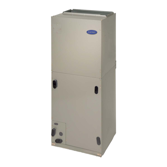
FB4C and FX4D models are R−410A Fan Coils designed for
installation flexibility. These units leave the factory compliant with
low leak requirements of less than 2% cabinet leakage rate at 0.5
inches W.C. and 1.4% cabinet leakage rate at 0.5 inches W.C. when
tested in accordance with ASHRAE 193 standard.
FB4CNF(018−048) uses a refrigerant piston metering device. A
TXV is used on FB4CNP and FX4D(018−061). All these fan coils
use a multi−tap ECM motor for efficiency. The units have be
designed for upflow, downflow (kit required), and horizontal
orientations,
including
applications.
These units require a field supplied air filter, and are designed
specifically for R−410A refrigerant air conditioners and heat
pumps as shipped. These units are available for systems of 18,000
.
through 60,000 BTUh nominal cooling capacity. Factory−
authorized, field − installed electric heater packages are available in
sizes 5 through 30kW. See Product Data literature for all available
accessory kits.
FAN COIL UNITS
FOR R−410A REFRIGERANT
SIZES 018 TO 061
WARNING
CAUTION
INTRODUCTION
manufactured
and
mobile
home
Advertisement
Table of Contents

Related Manuals for Carrier FB4CNP


Summary of Contents for Carrier FB4CNP
-
Page 1: Table Of Contents
FB4CNF(018−048) uses a refrigerant piston metering device. A and work gloves. Have a fire extinguisher available. Read these TXV is used on FB4CNP and FX4D(018−061). All these fan coils instructions thoroughly and follow all warnings or cautions use a multi−tap ECM motor for efficiency. The units have be included in literature and attached to the unit. -
Page 2: Heater Packages
HEATER PACKAGES B. Downflow Installation In this application, field conversion of the evaporator is required This unit may or may not be equipped with an electric heater using accessory downflow kit along with an accessory base kit. package. For units not equipped with factory−installed heat, a Use fireproof resilient gasket, 1/8 to 1/4−in (3 to 6 mm) thick, factory−approved, field−installed, UL listed heater package is between duct, unit, and floor. - Page 3 COIL MOUNTING BLOWER SCREW ASSEMBLY COIL FACTORY SHIPPED BRACKET HORIZONTAL LEFT APPLICATION COIL SUPPORT RAIL COIL SUPPORT DRAIN PAN RAIL SUPPORT BRACKET COIL BRACKET SLOPE COIL HORIZONTAL DRAIN PAN PRIMARY DRAIN HORIZONTAL LEFT DRAINPAN PRIMARY DRAIN AIR SEAL REFRIGERANT ASSEMBLY SECONDARY DRAIN CONNECTIONS HORIZONTAL LEFT...
-
Page 4: Step 3 - Air Ducts
6. Convert air−seal assembly for horizontal right. 4” (102mm) MAX a. Remove air−seal assembly from coil by removing 4 SECURE FAN COIL TO STRUCTURE screws. (See Fig. 6.) UNIT AWAY FROM WALL b. Remove air splitter (B) from coil seal assembly by remov- PIPE STRAP ing 3 screws. - Page 5 CAUTION FAN COIL THERMOSTAT (CONTROL) PROPERTY DAMAGE HAZARD Failure to follow this caution may result in product or property damage. If a disconnect switch is to be mounted on unit, select a location where drill or fastener will not contact electrical or refrigerant components.
- Page 6 Refer to outdoor unit wiring instructions for any additional wiring Tap 1 90 sec off delay procedure recommendations. Tap 2 Medium 90 sec off delay Transformer Information Tap 3 High 90 sec off delay Transformer is factory−wired for 230v operation. For 208v Tap 4 Electric heat †...
-
Page 7: Step 5 - Refrigerant Tubing Connection And Evacuation
FB4CNF units contain a factory installed piston with Teflon ring procedures for the condensate drains on both A−coil and for sizes 018 thru 048 only. The FB4CNP and FX4D(018−061) slope units. The vertical drains have an overflow hole size units come equipped with a R−410A refrigerant TXV. If a between the primary and secondary drain holes. -
Page 8: Step 8 - Accessories
should be pitched downward at a minimum slope of 1−in (25 mm) for every 10−ft (3 m) of length. Consult local codes for additional restrictions or precautions. Step 8 — Accessories Humidifier Connect humidifier and humidistat to fan coil unit as shown in Fig. 19 and Fig. -
Page 9: Start−Up Procedures
START−UP PROCEDURES FAN COIL THERMOSTAT (CONTROL) Refer to outdoor unit Installation Instructions for system start−up instructions and refrigerant charging method details. CAUTION UNIT COMPONENT HAZARD Failure to follow this caution may result in product damage. Never operate unit without a filter. Damage to blower motor or coil may result. - Page 10 AIRFLOW PERFORMANCE TABLES (cont) Table 4 – FB4C Airflow Performance (CFM) BLOWER MODEL & SIZE 0.10 0.20 0.30 0.40 0.50 0.60 SPEED Tap 5 Tap 4 FB4C 018 Tap 3 Tap 2 Tap 1 Tap 5 Tap 4 FB4C 024 / 025 Tap 3 Tap 2 Tap 1...
- Page 11 AIRFLOW PERFORMANCE TABLES (cont) Table 5 – FX4D Airflow Performance (CFM) EXTERNAL STATIC (in. wc) MODEL & BLOWER SIZE SPEED 0.10 0.20 0.30 0.40 0.50 0.60 Tap 5 Tap 4 FX4D 019 Tap 3 Tap 2 Tap 1 Tap 5 Tap 4 Tap 3 FX4D 025...
- Page 12 R−410A QUICK REFERENCE GUIDE R−410A refrigerant operates at 50−70 percent higher pressures than R−22. Be sure that servicing equipment and replacement components are designed to operate with R−410A refrigerant. R−410A refrigerant cylinders are rose colored. Recovery cylinder service pressure rating must be 400 psig, DOT 4BA400 or DOT BW400. R−410A refrigerant systems should be charged with liquid refrigerant.
Need help?
Do you have a question about the FB4CNP and is the answer not in the manual?
Questions and answers