Carrier FX4D Series Installation Instructions Manual
Fan coils
Hide thumbs
Also See for FX4D Series:
- Product data (17 pages) ,
- Service and maintenance instructions (33 pages) ,
- Installation instructions manual (12 pages)
Advertisement
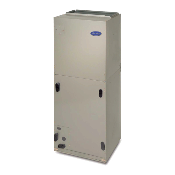
FX4D
FAN COILS
NOTE: Read the entire instruction manual before starting the installation.
SAFETY CONSIDERATIONS
Improper installation, adjustment, alteration, service, maintenance, or
use can cause explosion, fire, electrical shock, or other conditions which
may cause death, personal injury or property damage. Consult a
qualified installer, service agency, or your distributor or branch for
information or assistance. The qualified installer or agency must use
factory-authorized kits or accessories when modifying this product.
Refer to the individual instructions packaged with kits or accessories
when installing.
Follow all safety codes. Wear safety glasses, protective clothing and
work gloves. Have a fire extinguisher available. Read these instructions
thoroughly and follow all warnings or cautions included in literature and
attached to the unit. Consult local building codes and the current editions
of the National Electrical Code (NEC) NFPA 70.
In Canada, refer to the current editions of the Canadian Electrical Code
CSA C22.1.
Recognize safety information. This is the safety-alert symbol
you see this symbol on the unit and in instruction manuals, be alert to the
potential for personal injury.
Understand the signal words DANGER, WARNING, and CAUTION.
These words are used with the safety-alert symbol. DANGER identifies
the most serious hazards which will result in severe personal injury or
death. WARNING signifies hazards which could result in personal
injury or death. CAUTION is used to identify unsafe practices which
may result in minor personal injury or product and property damage.
NOTE is used to highlight suggestions which will result in enhanced
installation, reliability, or operation.
WARNING
!
ELECTRICAL OPERATION HAZARD
Failure to maintain proper clearances could result in personal injury or
death.
Before installing or servicing unit, always turn off all power to unit.
There may be more than 1 disconnect switch. Turn off accessory heater
power if applicable. Lock out and tag switch with a suitable warning
label.
CAUTION
!
CUT HAZARD
Failure to follow this caution may result in personal injury.
Sheet metal parts may have sharp edges or burrs. Use care and wear
appropriate protective clothing, safety glasses and gloves when
handling parts.
INTRODUCTION
Model FX4D is designed for flexibility and can be used for upflow,
horizontal, or downflow (kit required) and manufactured and mobile
home applications. These units are designed to meet the low air leak
requirements currently in effect. Because of this, the units need special
Installation Instructions
. When
attention in the condensate pan and drain connection area and when
brazing tubing. These units are designed specifically for Puronr
refrigerant and must be used only with Puronr refrigerant air
conditioners and heat pumps as shipped. These units are available for
systems of 18,000 through 60,000 Btuh nominal cooling capacity.
Factory-authorized, field-installed electric heater packages are available
in sizes 5 through 30kW. See Product Data literature for available
accessory kits.
HEATER PACKAGES
This unit may or may not be equipped with an electric heater package.
For units not equipped with factory-installed heat, a factory-approved,
field-installed, UL listed heater package is available from your
equipment supplier. See unit rating plate for a list of factory-approved
heaters. Heaters that are not factory approved could cause damage which
would not be covered under the equipment warranty. If fan coil contains
a factory-installed heater package, minimum circuit ampacity (MCA)
and maximum fuse/breaker may be different than units with a same size
field-installed accessory heater. The difference is not an error and is due
to calculation differences per UL guidelines.
INSTALLATION
CHECK EQUIPMENT
Unpack unit and move to final location. Remove carton taking care not
to damage unit. Inspect equipment for damage prior to installation. File
claim with shipping company if shipment is damaged or incomplete.
Locate unit rating plate which contains proper installation information.
Check rating plate to be sure unit matches job specifications.
MOUNT UNIT
Unit can stand or lie on floor, or hang from ceiling or wall. Allow space
for wiring, piping, and servicing unit.
IMPORTANT: When unit is installed over a finished ceiling and/or
living area, building codes may require a field-supplied secondary
condensate pan to be installed under the entire unit. Some localities may
allow as an alternative, the running of a separate, secondary condensate
line. Consult local codes for additional restrictions or precautions.
NOTE: Nuisance sweating may occur if the unit is installed in a high
humidity environment with low airflow.
UPFLOW INSTALLATION
If return air is to be ducted through a floor, set unit on floor over opening
and use 1/8 to 1/4-in (3 to 6 mm) thick fireproof resilient gasket between
duct, unit, and floor.
Side return is a field option on slope coil models. Cut opening per
dimensions. (See Fig. 1.) A field-supplied bottom closure is required.
DOWNFLOW INSTALLATION
In this application, field conversion of the evaporator is required using
accessory downflow kit along with an accessory base kit. Use fireproof
resilient gasket, 1/8 to 1/4-in (3 to 6 mm) thick, between duct, unit, and
floor.
Advertisement
Table of Contents

Related Manuals for Carrier FX4D Series


Summary of Contents for Carrier FX4D Series
- Page 1 FX4D FAN COILS Installation Instructions NOTE: Read the entire instruction manual before starting the installation. SAFETY CONSIDERATIONS attention in the condensate pan and drain connection area and when brazing tubing. These units are designed specifically for Puronr Improper installation, adjustment, alteration, service, maintenance, or refrigerant and must be used only with Puronr refrigerant air use can cause explosion, fire, electrical shock, or other conditions which conditioners and heat pumps as shipped.
-
Page 2: Horizontal Installation
FX4D: Installation Instructions POWER ENTRY FIELD SUPPLIED OPTIONS SUPPLY DUCT LOW VOLT ENTRY OPTIONS 019 - 049 21" (533 mm) FRONT SERVICE 24" (610mm) CLEARANCE UNIT 019, 025 17" (432 mm) A COIL 19" (483 mm) UNITS UPFLOW/DOWNFLOW SECONDARY DRAIN 1.5"... - Page 3 FX4D: Installation Instructions A-COIL HORIZONTAL LEFT PRIMARY SECONDARY DRAIN FIELD DRAIN SUPPLIED HANGING STRAPS 018-048 21" (533 mm) 060-060 24" (610 mm) FRONT SERVICE CLEARANCE UNIT (FULL FACE OF UNIT) LOW VOLT ENTRY OPTIONS 1.75" (44 mm) FILTER ACCESS CLEARANCE PRIMARY DRAIN SECONDARY...
- Page 4 FX4D: Installation Instructions COIL MOUNTING BLOWER SCREW ASSEMBLY COIL SUPPORT RAIL SLOPE COIL DRAINPAN PRIMARY DRAIN REFRIGERANT CONNECTIONS SECONDARY DRAIN A03001 Fig. 5 – Conversion for Horizontal Right Applications - Slope Coil REFRIGERANT AIR SEAL CONNECTIONS ASSEMBLY HORIZONTAL RIGHT APPLICATION COIL SUPPORT RAIL...
-
Page 5: Air Ducts
FX4D: Installation Instructions AIR DUCTS WARNING Connect supply-air duct over the outside of 3/4-in (19 mm) flanges provided on supply-air opening. Secure duct to flange, using proper ELECTRICAL SHOCK OR UNIT DAMAGE HAZARD fasteners for type of duct used, and seal duct-to-unit joint. If return-air Failure to follow this warning could result in personal injury, death, flanges are required, install factory-authorized accessory kit. - Page 6 FX4D: Installation Instructions When 2 stages are desired, cut W3 at the W2 wire nut, strip and FAN COIL THERMOSTAT reconnect per the thermostat kit instruction. (See Fig. 13.) When 3 stages are desired, cut the W2 wire nut off and discard. Strip W2, W3, and E and reconnect per thermostat kit instructions.
-
Page 7: Ground Connections
FX4D: Installation Instructions GROUND CONNECTIONS 2. Insert tube into sweat connection on unit until it bottoms. 3. Braze connection using silver bearing or non-silver bearing brazing NOTE: Use UL listed conduit and conduit connectors for connecting materials. Do not use solder (materials which melt below 800_F / supply wire(s) to unit to obtain proper grounding. -
Page 8: Cooling Mode
FX4D: Installation Instructions NOTE: When connecting condensate drain lines, avoid blocking filter NOTE: If unit is located in or above a living space where damage may access panel, thus preventing filter removal. After connection, prime result from condensate overflow, a field-supplied, external condensate both primary and secondary condensate traps. -
Page 9: Start-Up Procedures
FX4D: Installation Instructions FAN COIL FAN COIL THERMOSTAT HEAT PUMP THERMOSTAT (CONTROL) AIR COND. FAN HUMIDIFIER RELAY 115V HUMIDISTAT FAN HUMIDIFIER HUMIDISTAT 115V A09389 Fig. 21 – Wiring Layout of Humidifier to Fan Coil A09391 Fig. 20 – Wiring Layout of Humidifier to Heat Pump with Electric Heat START-UP PROCEDURES CARE AND MAINTENANCE... - Page 10 Horizontal applications of 043 - 061 sizes must have supply static greater than 0.20 in. wc. 4.Airflow above 400 cfm/ton on 049 - 061 size could result in condensate blowing off coil or splashing out of drain pan. © 2022 Carrier. All rights reserved. Edition Date: 10/22...
Need help?
Do you have a question about the FX4D Series and is the answer not in the manual?
Questions and answers