Advertisement
Table of Contents
- 1 Table of Contents
- 2 Safety Considerations
- 3 Introduction
- 4 Heater Packages
- 5 Installation
- 6 Air Ducts
- 7 Electrical Connections
- 8 Refrigerant Tubing Connection and Evacuation
- 9 Refrigerant Flow-Control Device
- 10 Condensate Drains
- 11 Accessories
- 12 Sequence of Operation
- 13 Start-Up Procedures
- 14 Care and Maintenance
- Download this manual
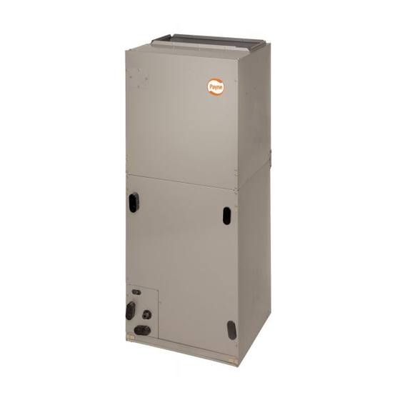
PF4MNB, PF4MNP
FAN COIL UNITS
SIZES 018 TO 061
NOTE: Read the entire instruction manual before starting the installation.
Safety Considerations
Improper installation, adjustment, alteration, service, maintenance, or
use can cause explosion, fire, electrical shock, or other conditions which
may cause death, personal injury or property damage. Consult a
qualified installer, service agency, or your distributor or branch for
information or assistance. The qualified installer or agency must use
factory-authorized kits or accessories when modifying this product.
Refer to the individual instructions packaged with kits or accessories
when installing.
Follow all safety codes. Wear safety glasses, protective clothing and
work gloves. Have a fire extinguisher available. Read these instructions
thoroughly and follow all warnings or cautions included in literature and
attached to the unit. Consult local building codes and the current editions
of the National Electrical Code (NEC) NFPA 70.
In Canada, refer to the current editions of the Canadian Electrical Code
CSA C22.1.
Recognize safety information. This is the safety-alert symbol
you see this symbol on the unit and in instruction manuals, be alert to the
potential for personal injury.
Understand the signal words DANGER, WARNING, and CAUTION.
These words are used with the safety-alert symbol. DANGER identifies
the most serious hazards which will result in severe personal injury or
death. WARNING signifies hazards which could result in personal
injury or death. CAUTION is used to identify unsafe practices which
may result in minor personal injury or product and property damage.
NOTE is used to highlight suggestions which will result in enhanced
installation, reliability, or operation.
WARNING
!
ELECTRICAL OPERATION HAZARD
Failure to maintain proper clearances could result in personal injury or
death.
Before installing or servicing unit, always turn off all power to unit.
There may be more than 1 disconnect switch. Turn off accessory heater
power if applicable.
CAUTION
!
CUT HAZARD
Failure to follow this caution may result in personal injury.
Sheet metal parts may have sharp edges or burrs. Use care and wear
appropriate protective clothing, safety glasses and gloves when
handling parts.
Installation Instructions
. When
Table of Contents
Safety Considerations . . . . . . . . . . . . . . . . . . . . . . . . . . . . . . . . . . . . . . . 1
Table of Contents . . . . . . . . . . . . . . . . . . . . . . . . . . . . . . . . . . . . . . . . . . 1
Introduction. . . . . . . . . . . . . . . . . . . . . . . . . . . . . . . . . . . . . . . . . . . . . . . 1
Heater Packages . . . . . . . . . . . . . . . . . . . . . . . . . . . . . . . . . . . . . . . . . . . 1
Installation . . . . . . . . . . . . . . . . . . . . . . . . . . . . . . . . . . . . . . . . . . . . . . . 2
Air Ducts. . . . . . . . . . . . . . . . . . . . . . . . . . . . . . . . . . . . . . . . . . . . . . . . . 5
Electrical Connections . . . . . . . . . . . . . . . . . . . . . . . . . . . . . . . . . . . . . . 5
Table 1 - Fan Speed Selection . . . . . . . . . . . . . . . . . . . . . . . . . . . . . . 7
Refrigerant Tubing Connection and Evacuation . . . . . . . . . . . . . . . . . . 7
Refrigerant Flow-Control Device . . . . . . . . . . . . . . . . . . . . . . . . . . . . . . 7
Condensate Drains . . . . . . . . . . . . . . . . . . . . . . . . . . . . . . . . . . . . . . . . . 7
Accessories . . . . . . . . . . . . . . . . . . . . . . . . . . . . . . . . . . . . . . . . . . . . . . . 8
Sequence of Operation . . . . . . . . . . . . . . . . . . . . . . . . . . . . . . . . . . . . . . 8
Start-Up Procedures . . . . . . . . . . . . . . . . . . . . . . . . . . . . . . . . . . . . . . . . 9
Care and Maintenance . . . . . . . . . . . . . . . . . . . . . . . . . . . . . . . . . . . . . . 9
Table 2 - Air Delivery Performance Correction Component Pressure
Drop (in. wc) at Indicated Airflow (Dry-to-Wet Coil) . . . . . . . . . . . . 9
Table 3 - Factory-Installed Filter Static Pressure Drop (in. wc) . . . . 9
Table 4 - Electric Heater Static Pressure Drop (in. wc). . . . . . . . . . 10
Table 5 - PF4MNP Airflow Performance (CFM) . . . . . . . . . . . . . . 10
Table 6 - PF4MNB Airflow Performance (CFM) . . . . . . . . . . . . . . 11
Introduction
PF4M models are R-410A Fan Coils designed for installation flexibility.
These units leave the factory compliant with low leak requirements of
less than 2% cabinet leakage rate at 0.5 inches W.C. and 1.4% cabinet
leakage rate at 0.5 inches W.C. when tested in accordance with
ASHRAE 193 standard.
A TXV is used on PF4MNP (018-060) and PF4MNB(019-061). All
these fan coils use a multi-tap ECM motor for efficiency. The units have
be designed for upflow, downflow (kit required), and horizontal
orientations, including manufactured and mobile home applications.
These units require a field supplied air filter, and are designed
specifically for R-410A refrigerant air conditioners and heat pumps as
shipped. These units are available for systems of 18,000 through 60,000
BTUh nominal cooling capacity. Factory- authorized, field - installed
electric heater packages are available in sizes 5 through 30kW. See
Product Data literature for all available accessory kits.
Heater Packages
This unit may or may not be equipped with an electric heater package.
For units not equipped with factory-installed heat, a factory-approved,
field-installed, UL listed heater package is available from your
equipment supplier. See unit rating plate for a list of factory-approved
heaters. Heaters that are not factory approved could cause damage which
would not be covered under the equipment warranty. If fan coil contains
a factory-installed heater package, minimum circuit ampacity (MCA)
and maximum fuse/breaker may be different than units with a same size
field-installed accessory heater. The differences is not an error and is due
to calculation difference per UL guidelines.
Advertisement
Table of Contents

Related Manuals for Carrier PF4MNB Series


Summary of Contents for Carrier PF4MNB Series
-
Page 1: Table Of Contents
PF4MNB, PF4MNP FAN COIL UNITS SIZES 018 TO 061 Installation Instructions NOTE: Read the entire instruction manual before starting the installation. Safety Considerations Table of Contents Improper installation, adjustment, alteration, service, maintenance, or Safety Considerations ........1 use can cause explosion, fire, electrical shock, or other conditions which Table of Contents . -
Page 2: Installation
PF4MNB, PF4MNP: Installation Instructions Installation IMPORTANT: When unit is installed over a finished ceiling and/or living area, building codes may require a field-supplied secondary Check Equipment condensate pan to be installed under the entire unit. Some localities may Unpack unit and move to final location. Remove carton taking care not allow as an alternative, the running of a separate, secondary condensate to damage unit. - Page 3 PF4MNB, PF4MNP: Installation Instructions COIL FACTORY SHIPPED BRACKET HORIZONTAL LEFT APPLICATION COIL SUPPORT RAIL DRAIN PAN SUPPORT BRACKET COIL BRACKET HORIZONTAL DRAIN PAN PRIMARY DRAIN HORIZONTAL LEFT AIR SEAL ASSEMBLY SECONDARY DRAIN HORIZONTAL LEFT REFRIGERANT CONNECTIONS A00072 Fig. 3 – A-Coil in Horizontal Left Application (Factory Configuration) COIL MOUNTING BLOWER SCREW...
- Page 4 PF4MNB, PF4MNP: Installation Instructions Downflow Installation 8. Align holes with tubing connections and condensate pan connections. Reinstall access panels and fitting panel. In this application, field conversion of the evaporator is required using 9. Make sure liquid and suction tube grommets are in place to prevent accessory downflow kit along with an accessory base kit.
-
Page 5: Air Ducts
PF4MNB, PF4MNP: Installation Instructions Air Ducts Connect supply-air duct over the outside of 3/4-in (19 mm) flanges provided on supply-air opening. Secure duct to flange, using proper fasteners for type of duct used, and seal duct-to-unit joint. If return-air flanges are required, install factory-authorized accessory kit. Use flexible connectors between ductwork and unit to prevent transmission of vibration. - Page 6 PF4MNB, PF4MNP: Installation Instructions Line Voltage Connections FAN COIL HEAT PUMP THERMOSTAT (CONTROL) If unit contains an accessory electric heater, remove and discard power (CONTROL) plug from fan coil and connect male plug from heater to female plug from unit wiring harness. (See Electric Heater Installation Instructions.) For units without electric heat: 1.
-
Page 7: Refrigerant Tubing Connection And Evacuation
PF4MNB, PF4MNP: Installation Instructions Ground Connections remain on tap 4. Speed-tap 5 is used for high static applications, but has a 0 second blower time delay pre-programmed into the motor. See NOTE: Use UL listed conduit and conduit connectors for connecting Airflow Performance tables for actual CFM. -
Page 8: Accessories
PF4MNB, PF4MNP: Installation Instructions performance, BOTH primary and secondary drain lines should be condensate will be noticeable. The owner of the structure must be installed and include properly-sized condensate traps (Fig. 15 informed that when condensate flows from the secondary drain or Fig. -
Page 9: Start-Up Procedures
PF4MNB, PF4MNP: Installation Instructions Electric Heat or Emergency Heat Mode FAN COIL THERMOSTAT (CONTROL) Thermostat closes R to W. W energizes electric heat relay(s) which completes circuit to heater element(s). Blower motor is energized through speed tap 4 (white wire). When W is de-energized, electric heat relay(s) opens. - Page 10 PF4MNB, PF4MNP: Installation Instructions Table 4 – Electric Heater Static Pressure Drop (in. wc) Sizes 018 - 037 Sizes 042 - 061 EXTERNAL STATIC EXTERNAL STATIC HEATER HEATER PRESSURE PRESSURE ELEMENTS ELEMENTS CORRECTION CORRECTION +.02 +.04 3, 5 +.01 8, 10 +.02 8, 10 9, 15...
- Page 11 PF4MNB, PF4MNP: Installation Instructions Table 6 – PF4MNB Airflow Performance (CFM) EXTERNAL STATIC (in. wc) Model & Size Blower Speed 0.10 0.20 0.30 0.40 0.50 0.60 Tap 5 Tap 4 PF4MNB 019 Tap 3 Tap 2 Tap 1 Tap 5 Tap 4 PF4MNB 025 Tap 3...
- Page 12 PF4MNB, PF4MNP: Installation Instructions NOTES Edition Date: 3/20 ©2020 Carrier Catalog No: IM-PF4MNB-P-01 Replaces: New Manufacturer reserves the right to change, at any time, specifications and designs without notice and without obligations.
Need help?
Do you have a question about the PF4MNB Series and is the answer not in the manual?
Questions and answers