Henny Penny 500 Operator's Manual
Pressure fryers
Hide thumbs
Also See for 500:
- Service manual (264 pages) ,
- Technical manual (236 pages) ,
- Operator's manual (78 pages)
Table of Contents
Advertisement
Advertisement
Table of Contents

Related Manuals for Henny Penny 500


Summary of Contents for Henny Penny 500
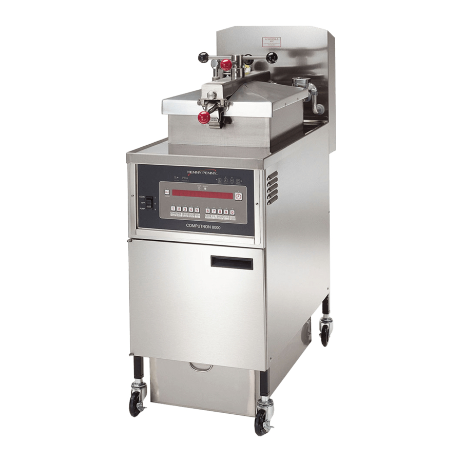
- Page 1 Henny Penny Pressure Fryers Model 500 Model 561 Model 600 OPERATOR’S MANUAL...
- Page 3 (2) years from date of original installation, will be repaired or replaced without charge F.O.B. factory, Eaton, Ohio, or F.O.B. authorized distributor. To validate this warranty, the registration card for the appliance must be mailed to Henny Penny within ten (10) days after installation.
- Page 5 Model 500/561/600 This manual should be retained in a convenient location for future reference. A wiring diagram for this appliance is located on the rear shroud cover of the control panel. Post in a prominent location, instructions to be followed if user smells gas. This information should be obtained by consulting the local gas supplier.
- Page 6 Model 500/561/600 Technical Data for CE Marked Products Nominal Heat Input: Natural (I ) = 21.1 KW (72,000 Btu/h) (Net) Natural (I ) = 21.1 KW (72,000 Btu/h) Natural (I ) = 21.1 KW (72,000 Btu/h) Natural (I ) = 21.1 KW (72,000 Btu/h) Liquid Propane (I ) = 21.1 KW (72,000 Btu/h)
-
Page 7: Table Of Contents
Model 500/561/600 TABLE OF CONTENTS Section Page Section 1. INTRODUCTION ....................... 1-1 1-1. Pressure Fryer ..................... 1-1 1-2. Proper Care ......................1-1 1-3. Assistance ......................1-1 1-4. Model Variations ....................1-1 1-5. Safety ......................... 1-2 Section 2. INSTALLATION ......................2-1 2-1. - Page 8 3-18. Lid Lubrication ....................3-33 3-19. Limit Stop Adjustment ..................3-34 3-20. Cleaning the Safety Relief Valve ................3-35 3-21. Check & Tighten Element Spreader Bars (Models 500 & 561 only) ..... 3-36 3-22. Seasonal Shutdown ..................... 3-37 3-23. Cut-Up Fried Chicken ..................3-37 3-24.
-
Page 9: Section 1. Introduction
Model 500/561/600 SECTION 1. INTRODUCTION 1-1. PRESSURE FRYER The Henny Penny Pressure Fryer is a basic unit of food processing equipment. It has found wide application in institutional and commercial food service operations. P-H-T A combination of pressure, heat, and time is automatically controlled to produce the optimum in a tasty, appealing product. -
Page 10: Safety
Model 500/561/600 1-5. SAFETY The Henny Penny Pressure Fryer has may safety features incorporated. However, the only way to ensure a safe operation is to fully understand the proper installation, operation, and maintenance procedures. The instructions in this manual have been prepared to aid you in learning the proper procedures. -
Page 11: Section 2. Installation
SECTION 2. INSTALLATION This section provides the installation instructions for the electric and 2-1. INTRODUCTION gas models of Henny Penny Pressure Fryers. Installation of this unit should be performed only by a qualified service technician. Do not puncture the fryer with any objects such as drills or screws as electrical shock or component damage could result. - Page 12 Model 500/561/600 2-2. UNPACKING INSTRUCTIONS (Continued) 5. Remove the four leg bolts from the wooden shipping base. Remove and discard the wooden base. 6. Thread the shipping bolts back into the legs to provide leveling adjustment feet. If ordered, install casters into the legs, with the locking casters in front.
-
Page 13: Selecting The Fryer Location
Model 500/561/600 2-3. SELECTING THE FRYER The proper location of the fryer is very important for operation, LOCATION speed, and convenience. Choose a location which will provide easy loading and unloading without interfering with the final assem- bly of food orders. Operators have found that frying from raw to finish, and holding the product in a warmer provides fast continuous service. -
Page 14: Ventilation Of Fryer
Model 500/561/600 2-5. VENTILATION OF FRYER The fryer must be located with provision for venting into adequate exhaust hood or ventilation system. This is essential to permit efficient removal of the flue gases and frying odors. Special precaution must be taken in designing an exhaust canopy to avoid interference with the operation of the fryer. -
Page 15: Gas Supply
Model 500/561/600 2-6. GAS SUPPLY The gas fryer is factory available for either natural or propane gas. Check the data plate on the right side panel of the cabinet to deter- mine the proper gas supply requirements. The minimum supply for natural gas is 7 inches water column (1.7 kPa), and 10 inches water... -
Page 16: Gas Piping
Model 500/561/600 2-7. GAS PIPING Please refer below for the recommended hookup of the fryer to main gas line supply. To avoid possible serious personal injury: • Installation must conform with American National Standard Z223.1-Latest Edition National Fuel Gas Code and the local municipal building codes. - Page 17 Model 500/561/600 2-7. GAS PIPING (Henny Penny Part No. 19921), which complies with (Continued) ANSI standard Z21.41, or CAN 1-6.9. Also adequate means must be provided to limit the movement of the fryer without depending on the connector and quick- disconnect device or its associated piping to limit the fryer movement.
- Page 18 Model 500/561/600 2-7. GAS PIPING (Continued)
-
Page 19: Gas Leak Test
REGULATOR SETTING Natural: 3.5 inches water column (0.87 kPa) Propane: 10.0 inches water column (2.49 kPa) The gas pressure regulator has been set by Henny Penny and is not to be adjusted by the user. 2-10. GAS PILOT & BURNER... -
Page 20: Pilot Flame Adjustment
1. Turn main power switch to OFF. 2. Depress the gas control valve knob lightly and turn to the OFF position. The pilot flame is preset at the factory. If adjustment is necessary, 2-11. PILOT FLAME contact your local independent Henny Penny distributor. ADJUSTMENT 2-10... -
Page 21: Pressure Regulator Adjustment (Gas Only)
The gas regulator is preset at the factory at 3.5 inch water column REGULATOR (0.87 kPa) for natural gas (10.0 inch (2.49 kPa) for propane). If ADJUSTMENT adjustment is necessary, contact your local independent Henny Penny (GAS ONLY) distributor. The electric fryer is available from the factory wired for 208, 220/240, 2-13. -
Page 22: Electrical Requirements (Gas Fryer)
(unearthed) conductors. The main power switch on this appliance does not disconnect all line conductors. Each Henny Penny pressure fryer was completely checked and tested 2-15. TESTING THE FRYER prior to shipment. However, it is good practice to check the unit again after installation. -
Page 23: Checking The Heating Elements (Electric Fryer)
Model 500/561/600 1. Place a cool, damp cloth on the heating elements. 2-17. CHECKING THE HEATING ELEMENTS 2. With the lid open, momentarily turn the thermostat to a setting of (ELECTRIC FRYERS) 200°F (93°C). Do not leave the thermostat on for more than 10 seconds when the elements are not covered with shortening or the elements might be damaged. -
Page 24: Checking The Filter Pump
The electric motor bearings are permanently lubricated. DO NOT LUBRICATE. This completes the testing cycle. If any of the functions did not occur, recheck the installation. If a problem persists, refer to other sections of this manual or call an authorized Henny Penny distributor. 2-14... -
Page 25: Final Installation Check - Test Frying
Model 500/561/600 2-21. FINAL INSTALLATION The final check to ensure a proper installation involves test frying. This CHECK - TEST gives the installer an opportunity to observe the actual cooking opera- FRYING tion of the pressure fryer. Before the actual cooking operation and adding shortening to the frypot, be sure frypot, filter screen assembly, and drain pan are cleaned. -
Page 26: Operational Checks
Model 500/561/600 2-21. FINAL INSTALLATION CHECK - TEST FRYING (Continued) Step 9 LID MUST BE LATCHED PROPERLY OR PRESSUR- IZED SHORTENING AND STEAM MAY ESCAPE FRYPOT. SEVERE BURNS WILL RESULT. 9. Close the lid. Be sure the lid has been securely latched. - Page 27 Model 500/561/600 2-22. OPERATIONAL 4. Turn the timer switch to the OFF position. CHECKS (Continued) • The red arrow will reset to the previous time setting, in this case, 8 minutes. 5. When all the steam pressure has exhausted (observe pressure gauge) open the lid.
- Page 28 Model 500/561/600 THIS PAGE INTENTIONALLY LEFT BLANK. 2-18...
-
Page 29: Section 3. Operating Instructions
Model 500/561/600 SECTION 3. OPERATING INSTRUCTIONS 3-1. OPERATING COMPONENTS The images at the end of this section, identify all the operator controls and the major components of the pressure fryer. Item Description Function Main Power Switch A three-way switch with center OFF position; move the switch to (POWER/OFF/PUMP) the POWER position (left) to operate the fryer;... -
Page 30: Operating Components
Model 500/561/600 3-1. OPERATING COMPONENTS (Continued) Item Description Function Condensation Drain This channels the moisture, that collects on the lid liner when the Channel lid is opened, into the drain line and prevents the moisture droplets from falling into the shortening... - Page 31 Model 500/561/600 3-1. OPERATING COMPONENTS (Continued) Item Description Function Safety Relief Valve Ring DO NOT PULL THIS RING. SEVERE BURNS FROM THE STEAM WILL RESULT. Pressure Gauge Indicates the pressure inside the frypot Solenoid Valve An electromechanical device that causes pressure to be held in the frypot;...
- Page 32 Model 500/561/600 3-1. OPERATING COMPONENTS (Continued) Item Description Function Filter Union Connects the filter to the filter pump, and allows easy removal of the filter and drain pan Filter Valve When the power switch is in the PUMP position, this two-way...
- Page 33 Model 500/561/600 ELECTRIC MODEL Figure 3-1. Operating Controls...
- Page 34 Model 500/561/600 GAS MODEL Figure 3-2. Operating Controls...
- Page 35 Model 500/561/600 Figure 3-6. Operating Controls Figure 3-3. Operating Controls Figure 3-4. Operating Controls Figure 3-7. Operating Controls Figure 3-5. Operating Controls Figure 3-8. Operating Controls...
-
Page 36: Start-Up (Preheat) Procedures
11. After the shortening temperature has stabilized for a minimum of 30 minutes, check the shortening temperature using a good deep fat thermometer (Henny Penny part number 12106). If off more than 5ºF, refer to the technical manual or call your local independent Henny Penny distributor. -
Page 37: Filling Or Adding Shortening
Model 500/561/600 12. If the shortening was not filtered the night before at shutdown, it 3-2. START-UP (PREHEAT) should be filtered now, after the shortening reaches the frying PROCEDURES temperature (325°F (163°C)) and before the fryer is used. Refer (Continued) to Filtering of Shortening Section. -
Page 38: Care Of The Shortening
To avoid severe burns when pouring hot shortening into frypot, wear gloves and take care to avoid splashing. 2. The electric model 500 requires 48 lbs. (21.8 kg) of liquid shortening, and the model 561 requires 65 lbs. (29.5 kg). The gas model requires 43 lbs. -
Page 39: Frying Procedure
4. Do not overload the baskets with product (12 lbs. (5.4 kg.) for SHORTENING (Continued) model 600 fryers; 14 lbs (6.4 kg.) for model 500 fryers and 18 lbs. (8.2 kg.) for the model 561) or place product with extreme moisture content into baskets. - Page 40 Model 500/561/600 3-5. FRYING PROCEDURE (Continued) 1. Take the chicken parts, either 4 or 5 cut-up chickens, from the cooler and place in a scullery sink. Wash the chicken and, at this point, break the thigh from the joint of the backbone.
- Page 41 Step 14 tor line. The maximum load size is 12 lbs. (5.4 kg.) for model 600 fryers; 14 lbs (6.4 kg.) for model 500 fryers and 18 lbs. (8.2 kg.) for the model 561. Failure to follow these instructions could result in a fire and/or damage to the fryer.
- Page 42 Model 500/561/600 3-5. FRYING PROCEDURE 15. Lift the basket slightly out of the shortening and shake it, causing (Continued) the pieces to separate. Return the basket to the shortening. Doing this will prevent white spots on the finished product. 16. Remove the basket handle and close the lid quickly.
- Page 43 Model 500/561/600 3-5. FRYING PROCEDURE 21. After the pressure drops to zero, turn the spindle (Continued) counterclockwise approximately one turn. Do not spin or flip the spindle cross arm when opening the lid. Damage to the acme nut inside the crossbar could result.
-
Page 44: Regular Maintenance Schedule
Model 500/561/600 3-6. REGULAR MAINTENANCE As in all food service equipment, the Henny Penny pressure fryer does SCHEDULE require care and proper maintenance. The table below provides a summary of scheduled maintenance. Procedure Frequency Filter pump motor protector- As required... -
Page 45: Filtering Of Shortening
4. As the shortening drains from the frypot, use fryer brushes (Henny Penny part number 12105 includes both brushes) to clean the side of the frypot and the heating elements (if electric unit). - Page 46 Model 500/561/600 3-8. FILTERING OF 5. When all of the shortening has drained, scrape or brush the sides SHORTENING and the bottom of the frypot. (Continued) 6. Rinse the frypot as follows: a. Close the drain valve. b. Open the filter valve.
- Page 47 Model 500/561/600 3-8. FILTERING OF b. While holding the wooden handle, make sure the hose nozzle SHORTENING is pointed down into the bottom of the frypot. Pull the lid (Continued) down over the nozzle, close the filter valve, and move the main power switch to the PUMP position.
- Page 48 Model 500/561/600 3-8. FILTERING OF 9. When the pump is pumping air only, the shortening in the frypot SHORTENING will appear to be boiling. Close the filter valve first and then (Continued) move the main power switch from PUMP to OFF. This will keep the filter pump and lines from filling up with shortening.
-
Page 49: Cleaning The Optional Crumb Pan
Model 500/561/600 3-9. CLEANING THE The crumb pan allows improved filtration process because finer, hard OPTIONAL CRUMB PAN to filter particles are now retained within the pan. Crumb accumulation within the filter pan is reduced, and it is quicker to pump the shortening back into the frypot. -
Page 50: Filter Pump Problem Prevention
Model 500/561/600 The following steps will help prevent filter pump problems: 3-10. FILTER PUMP PROBLEM Make certain the charcoal filter is installed with the smooth PREVENTION side down and the arms on the frame are clamped down over the protrusions on the outside of the frame. - Page 51 Model 500/561/600 3-11. CHANGING THE FILTER ENVELOPE (Continued) 6. Unthread the suction standpipe from the screen assembly. Step 7 7. Remove the crumb catcher and clean thoroughly with soap and water. Rinse thoroughly with hot water. Step 8 8. Remove the filter clips and discard the filter envelope.
- Page 52 Model 500/561/600 3-11. CHANGING THE FILTER ENVELOPE (Continued) 11. Slide the screens into a clean filter envelope. 12. Fold the corners in and then double fold the open end. 13. Clamp the envelope in place with the two filter retaining clips.
-
Page 53: Changing The Charcoal Filter
Model 500/561/600 3-12. CHANGING THE The charcoal filter should be changed every day or whenever it be- comes clogged with crumbs. Proceed as follows: CHARCOAL FILTER 1. Move the main power switch to the OFF position. 2. Remove and empty the condensation drain pan. -
Page 54: Cleaning The Frypot
Model 500/561/600 3-12. CHANGING THE CHARCOAL FILTER (Continued) 8. Remove and discard old filter pad. Clean and dry pan, frame, and grid thoroughly. 9. Place grid, frame and new charcoal filter pad in assembly with smooth side facing the grid and secure with clips. - Page 55 4. Fill the frypot to the level indicator with hot water. Add 4 to 6 ounces of fryer cleaner (Henny Penny part number 12101) to the water and mix thoroughly. The fry basket can be placed inside frypot for cleaning.
- Page 56 7. Let the cleaning solution stand for 15 to 20 minutes with the thermostat off. 8. Using the fryer brush (Henny Penny part number 12105), scrub the inside of the frypot, the lid liner, and around the countertop of the fryer.
-
Page 57: Cleaning The Deadweight Assembly
Step 3 Failure to clean the deadweight assembly daily could result in the fryer building too much pressure. Severe injuries and burns could result. 3. Clean the exhaust tube with stainless steel brush (Henny Penny part number 12147). 3-29... -
Page 58: Night Closing Procedures
Model 500/561/600 3-14. CLEANING THE DEADWEIGHT ASSEMBLY (Continued) 4. Clean the deadweight cap and weight in hot detergent water. Make certain to thoroughly clean the inside of the valve cap and the deadweight. 5. Clean the deadweight orifice and the inside of the deadweight assembly body with a clean lint-free cloth. -
Page 59: Operating Instructions For Optional Direct-Connect Shortening System
Model 500/561/600 3-16. OPERATING INSTRUC- 1. Connect the female quick disconnect, that is attached to TIONS FOR OPTIONAL the hose in the rear of the fryer, to the correct male quick DIRECT-CONNECT disconnect at the wall. Once attached, the hose can SHORTENING SYSTEM remain connected unless the fryer is moved. -
Page 60: Reversing The Lid Gasket
Model 500/561/600 3-17. REVERSING THE Reversing the lid gasket helps to prevent early failure of lid gasket LID GASKET and the loss of pressure during a cook cycle. 1. Back the 4 lid liner screws (2 on each side) out about 1/2 inch (12.7 mm). -
Page 61: Lid Lubrication
Model 500/561/600 3-18. LID LUBRICATION To extend the life of lid components, lubricate the ball seat and spindle, following the steps below. Close and latch the lid, and turn the spindle counterclockwise until it stops. Press down on the front of the cross bar, pull out the release pin, lift the latch, and raise the cross bar. -
Page 62: Limit Stop Adjustment
Model 500/561/600 3-19. LIMIT STOP To extend the life of the lid gasket and help prevent steam ADJUSTMENT leakage, check the limit stop adjustment quarterly, following the steps below. Close and latch lid, and turn spindle counterclockwise until it stops. -
Page 63: Cleaning The Safety Relief Valve
Model 500/561/600 3-19. LIMIT STOP Turn the inner collar counterclockwise until it stops against the ADJUSTMENT bottom hub of the spindle. (Continued) Tighten Allen screws. If the lid cover fails to seal properly, steam escapes from around the gasket during frying. Readjust the limit stop, this time turning the spindle 1 full turn after the initial contact of the lid gasket with the frypot rim (step 5). -
Page 64: Check & Tighten Element Spreader Bars (Models 500 & 561 Only)
5/16” socket or wrench, tighten all the element spreader screws. If the bolts or spreaders are missing or damaged, order kit no. 14685 from your nearest Henny Penny distributor. Pump shortening back into frypot and unit is now ready for use. -
Page 65: Seasonal Shutdown
3. Bread the pieces in advance (if using Henny Penny Fryer Breading Mix) so that the breaded chicken will be held at least 30 minutes before frying. Breading in advance will give the breading an opportunity to permeate the meat and adhere better to the product. -
Page 66: Chicken Quarters
2. Bread the pork chops (4 oz. portion, 1/2-inch to 3/4-inch VEAL CUTLETS (.11 kg, 12.7-19 mm) thick)with the Henny Penny Fryer Mix. 3. Fry at 315°F (157°C) for 5 minutes. If the chops are larger, allow an additional minute for each 2 ounce (.06 kg) increase per portion. -
Page 67: Top Sirloin Steak And Filet Mignon
Model 500/561/600 3. The ribs should be fried for 13 minutes at 275°F (135°C). 3-2. BARBECUED RIBS (Continued) 4. Ribs should then be brushed well on both sides with barbecue sauce, or placed in a pan of warm sauce. 5. Hold ribs in a sauce at 150ºF (66°C), for 30 minutes so flavor can permeate. -
Page 68: Rock Lobster Tail
Model 500/561/600 3-34. ROCK 1. Clean, wash, and drain. LOBSTER TAIL 2. Fry for 6 minutes at 315°F (157°C). 1. Use U.S. No. 1 grade Idaho potatoes, unpeeled. 3-35. POTATOES Wash and cut into 8 wedges. Drain and bread. 2. Fry for 8 minutes at 315°F (157°C). If smaller potatoes are used, time may be reduced. -
Page 69: Section 4. Troubleshooting
Model 500/561/600 SECTION 4. TROUBLESHOOTING 4-1. TROUBLESHOOTING GUIDE Problem Cause Correction • Fryer plugged in Power switch ON but fryer • Open Circuit • Check breaker or fuse at wall completely inoperative • Turn OFF and allow fryer to cool to Pressure not exhausting at •... -
Page 71: Glossary
Model 500/561/600 G L O S S A R Y HENNY PENNY PRESSURE FRYERS air valve a valve that allows air into the filter lines when the pump is on in the mixing mode on eight head fryers airflow switch a switch that senses the amount of airflow coming from the blower;... - Page 72 Model 500/561/600 data plate a label or plate located on the right side panel of the fryer that indicates the fryer type, serial number, warranty date, and other information deadweight a metal cylinder that works with the orifice to regulate the amount of steam entering the...
- Page 73 Model 500/561/600 flashpoint the temperature at which shortening ignites frypot the interior portion of the fryer that holds the shortening and the product while cooking frypot collar the top flat surface area around the fryer lid gas control valve an automatic dual controller that controls gas to both pilot lights and gas (gas fryers only) pressure to burners on fryers;...
- Page 74 Model 500/561/600 pilot orifice a controlled opening for the pilot light located on the burner assembly (gas fryers only) pilot light a small flame that remains burning even when the fryer is not in use; the flame (gas fryers only)
- Page 75 Model 500/561/600 THIS PAGE INTENTIONALLY LEFT BLANK.
- Page 76 Model 500/561/600...
- Page 77 Model 500/561/600 For Sales or Service Please Contact The Nearest Henny Penny Distributor 1&2. General Services Barnett Group PHT Systems ISI Commercial Refrigeration 101 Mystic Ave. 2089 York Ave. 1801 Old Highway 8 640 West 6th St. Medford, MA 02155...
- Page 78 Model 500/561/600...
- Page 79 Henny Penny International Distributor Network U.S. Headquarters Estonia Iceland Bulgaria Henny Penny Corporation Sisustaja As A. Karlsson H. F. E.C.E. - CAIX S.A.R.L. 1219 U.S. Route 35 West Tihniku 5 Brautarholti 28 23A Rue Oborichte Eaton, OH 45320 USA 11625 Tallinn, Estonia...
- Page 80 Lebanon Netherlands Saudi Arabia Taiwan Pro Kitchen Engelen-Heere B.V. Commercial Center Feco Corporation Cahlfoun Building Overschiese Dorpstraat 61 Development & Economy 420, 11 F Keelung Rd. Kaslik - Main Road 3043 CN Rotterdam, Holland P.O. Box 1210 Sec. 1 Postal Code 110 PO Box 1066 Jounieh Telephone: 010-422-30-77 Jeddah 21431, Saudi Arabia...
Need help?
Do you have a question about the 500 and is the answer not in the manual?
Questions and answers