Henny Penny CFA 600 Operator's Manual
Cfa pressure fryer
Hide thumbs
Also See for CFA 600:
- Service manual (270 pages) ,
- User manual (44 pages) ,
- Technical manual (236 pages)
Table of Contents
Advertisement
Advertisement
Table of Contents

Related Manuals for Henny Penny CFA 600


Summary of Contents for Henny Penny CFA 600
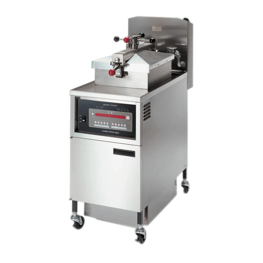
- Page 1 Henny Penny CFA Pressure Fryer Electric Model 500 Gas Model 600 OPERATOR’S MANUAL...
- Page 3 Do not obstruct the flow of combustion and ventilation air. Adequate clearance must be left all around appliance for sufficient air to the combustion chamber. The Model 600 fryer is equipped with a continuous pilot. But fryer can not be operated without electric power. Fryer will automatically return to normal operation when power is restored.
- Page 4 Model 500/600...
-
Page 5: Table Of Contents
Safety ... 1-2 Section 2. INSTALLATION ... 2-1 Introduction ... 2-1 Unpacking Instructions ... 2-1 Selecting the Fryer Location ... 2-2 Leveling the Fryer ... 2-3 Ventilation of Fryer ... 2-3 Gas Supply ... 2-5 Gas Leak Test ... 2-6 Gas Pressure Regulator Settings ... -
Page 6: Section Page
Check & Tighten Element Spreader Bars (Model 500 only) ... 4-7 Section 5.TROUBLESHOOTING Introduction ... 5-1 Troubleshooting ... 5-1 Diagnostic Mode Details ... 5-10 Information Mode Details ... 5-26 GLOSSARY ... G-1 Fryer Specs Page Warranty TABLE OF CONTENTS Model 500/600 Page... -
Page 7: Introduction
1-1. INTRODUCTION SECTION 1. INTRODUCTION The Henny Penny pressure fryer uses a combination of pressure, heat, and time to produce a quality product. The advantage of this type fryer is the pressure allows the product to be cooked with less heat and less time than the conventional open-type fryers. -
Page 8: Proper Care
1-2. PROPER CARE 1-3. ASSISTANCE 1-4. SAFETY As in any unit of food service equipment, the Henny Penny pressure fryer does require care and maintenance. Requirements for the maintenance and cleaning are contained in this manual and must become a regular part of the operation of the unit at all times. -
Page 9: Installation
2-1. INTRODUCTION 2-2. UNPACKING INSTRUCTIONS SECTION 2. INSTALLATION This section provides the installation instructions for the Henny Penny pressure fryer. Installation of this unit should be performed only by a qualified service technician. Do not puncture the fryer with any objects such as drillsor screws as electrical shock or com- ponent damage could result. - Page 10 Take care when moving the fryer to prevent personal injury. The fryer weighs approximately 300 lb (136 kg). 8. Tilt the fryer to one side so one side of the fryer frame is raised up off of the skid. 9. While one person holds the unit, another person hits the vertical wooden supports with a hammer pushing them under the fryer.
-
Page 11: Selecting The Fryer Location
Landing or dumping tables should be provided next to, at least, one side of the fryer. Keep in mind the best efficiency will be obtained by a straight line operation, i.e., raw in one side and finished out the other side. -
Page 12: Leveling The Fryer
Restraining ties may be used for stabilization. For proper operation, the fryer should be level from side to side and front to back. Place a level on the flat areas around the frypot collar, then adjust the leveling bolts or casters until the unit is level. - Page 13 Model 500/600 2-4. VENTILATION 0F FRYER (Continued)
-
Page 14: Gas Supply
2-6. GAS SUPPLY The gas fryer is factory available for either natural or propane gas. Check the data plate behind the front door of the fryer to determine the proper gas supply requirements. Do not attempt to use any gas other than that specified on the data plate. -
Page 15: Gas Leak Test
Standard for Connectors for Moveable Gas Appliances, ANSI Z21.6, or CAN/CSA 6.16, with a quick- disconnect coupling (Henny Penny Part No. 19921), which complies with ANSI standard Z21.41, or CAN 1-6.9. Also adequate means must be provided to limit the movement of the fryer without depending on the connector and quickdisconnect device or its associated piping to limit the fryer movement. - Page 16 Model 500/600...
-
Page 17: Gas Pressure Regulator Settings
Natural: 3.5 inches water column Propane: 10.0 inches water column The gas pressure regulator has been set by Henny Penny and is not to be adjusted by the user. Lighting Procedure - Solid State Ignition 1. Turn main power switch to OFF position. -
Page 18: Gas Pilot & Burner Lighting And Shutdown Procedures
11. Fill the frypot with peanut oil to the proper level. 12. The fryer is now ready for operation. The pilot flame is preset at the factory. If adjustment is neces- sary, contact your local independent Henny Penny distributor. Shutdown Procedure 1. Turn main power switch to OFF. -
Page 19: Pressure Regulator Adjustment (Gas Only)
(10.0 inch (2.49 kPa) for propane). If adjustment is necessary, contact your local independent Henny Penny distributor. The gas fryer requires 120 single phase, 60 Hertz, 10 or 5 amp, 2 wire + ground service. The gas fryer is factory equipped with a grounded cord and plug for your protection against shock and should be plugged into a 3 prong grounded receptacle. -
Page 20: Section 2. Installation
A separate disconnect switch with proper capacity fuses or breakers must be installed at a convenient location between the fryer and the power source. It should be an insulated copper conductor rated for 600 volts and 90 C. -
Page 21: Operation
(See Figure 3-1) Failure to clean the deadweight assembly daily could result in the fryer building too much pressure. Severe injuries and burns could result. An ASME approved, spring loaded valve, set at 14.5 psi; in the event the deadweight valve becomes clogged, this safety valve releases excess pressure, keeping the frypot chamber at 14.5 psi;... - Page 22 3-1. OPERATING COMPONENTS (Continued) Safety Relief Valve Ring Pressure Gauge Solenoid Valve Drain Valve Drain Interlock Switch Condensation Drain Pan Lid Latch DO NOT PULL THIS RING. SEVERE BURNS FROM THE STEAM WILL RESULT. (SEE FIGURE 3-1) Indicates the pressure inside the frypot; Figure 3-1 An electromechanical device that allows pressure to be held in the frypot;...
- Page 23 3-1. OPERATING COMPONENTS (Continued) High Limit Red Reset Button Figure 3-2 Gas Control Valve (Model 600) Spindle Assembly Lid Limit Stop Filter Drain Pan Filter Union Filter Valve Contactors (Model 500) A control that senses the temperature of the shortening; if the temperature of the shortening exceeds the safe operating limit, this control opens and shuts off the heat to the frypot;...
-
Page 24: Operating Controls
Lights when the peanut oil temperature is 5°F below setpoint to 15°F above the setpoint, signaling product can now be cooked Press to display current fryer information and status; if pressed in the Program Mode, shows previous settings; pressing this along... - Page 25 A 3-way switch with a center OFF position; turn the switch to COOK to operate the fryer; turn the switch to PUMP to oper- ate the filter pump; certain conditions that must be met before operating the filter pump and are covered later in this section Unit model number and the control’s hardware and software...
-
Page 26: Clock Set
3-3. CLOCK SET Upon initial start-up or PC board replacement, if automatically appears in the display, skip steps 1, 2 and 3. 1. Press and hold for 5 seconds until display. 2. Release , then press “ENTER CODE” shows in display. 3. - Page 27 3-3. CLOCK SET (Continued) 14. Press . Display shows “CS-6” along with “1.AM/PM”. “1.AM/PM” is 12 hour time, to change. 16. Press . Display shows “CS-7” SAVINGS ADJ” along with “2.US”. 17. Press to change to the following: “1.OFF” = No automatic adjustments for Daylight Savings Time.
-
Page 28: Diagnostic Mode And Special Functions
See Diagnostic Mode Details Section. Peanut Oil Life Function Based on the number of Cook Cycles of specific products and the amount of time the fryer idles, the controls tell the Operator when to change the peanut oil. “CHANGE OIL SOON”... - Page 29 The rate of temperature rise or fall e. Date and time After 5 seconds, the control exits the Status Mode and the pressure fryer returns to normal operation. Peanut Oil Filter Enforcement Prevents the Operator from exceeding the set number of Cook Cycles before filtering the peanut oil.
- Page 30 3-4. DIAGNOSTIC MODE AND SPECIAL FUNCTIONS (Continued) 3-10 Information Mode This mode gathers and stores historic information on the fryer and Operator performance. Press “*INFO MODE*” shows on display. Press steps and press to view the statistics within each step.
-
Page 31: Warnings And Error Messages
CANCEL button will not stop this warning; once the peanut oil temperature drops to set- point temperature, the alarm automatically stops Check ventilation louvers on side of fryer for obstructions; if louvers are clear, have PC board checked; check cooling fan if present. - Page 32 Have the contactors and PC board checked This error code could be displayed even with the COOK/PUMP switch turned OFF. Unplug fryer or shut off the wall circuit breaker to disconnect electrical power to fryer. Turn the COOK/PUMP switch OFF and back to COOK;...
-
Page 33: Error Codes
Have COOKPUMP switch checked, along with its wiring; have I/O board checked Have the 14-pin cable connector checked or have the fryer checked for a short to ground in components such as the drain switch, solenoid, or high limit and wiring... -
Page 34: Filling Or Adding Peanut Oil
Fire or damage to the frypot could result. 1. Henny Penny recommends using a high quality frying peanut oil in the pressure fryer. Some low grade peanut oils have a high mois- ture content which causes foaming and boiling over. - Page 35 Fire or damage to the frypot could result. 1. Henny Penny recommends using a high quality frying peanut oil in the pressure fryer. Some low grade peanut oils have a high mois- ture content which causes foaming and boiling over.
-
Page 36: Basic Operation
3-16 The following procedures should be followed on the initial start-up of the fryer, and each time the fryer is brought back into operation from a cold or shut down condition. These are basic, general instructions. 1. Check to see that the COOK/PUMP switch is turned OFF. - Page 37 600 fryers; 14 lbs (6.4 kg.) for model 500 fryers. Failure to follow these instructions could result in a fire and/or damage to the fryer. 13. Close the lid quickly, latching the lid. 14. Tighten the lid spindle clockwise, sealing the lid. Align the red knob on the spindle with the red knob on the latch.
- Page 38 16. Within a few minutes, the pressure gauge reading should increase to the OPERATING ZONE. If not, recheck the Installation and Operation procedures. 17. Near the end of the Cook Cycle, the fryer automatically depressurizes. Then at the end of the Cook Cycle, an alarm sounds. Press to stop the alarm.
-
Page 39: Care Of Peanut Oil
3-7. BASIC OPERATION (Continued) 3-8. CARE OF PEANUT OIL 19. Unlatch and raise the lid quickly to allow most of the condensation on the lid to drain through the drain channel and not into the peanut oil. Do not let the lid slam up against its backstop because this could damage the hinge. -
Page 40: Filtering Of Shortening
The filter drain pan must be as far back under fryer as it will go, and the cover in place. Be sure the hole in the cover lines up with the drain before opening the drain. - Page 41 (Continued) Figure 3-7 Figure 3-8 4. As the peanut oil drains from the frypot, use fryer brushes (Henny Penny part no. 12105-includes both brushes) to clean the frypot and heating elements (if electric unit). Use L-shaped brush to clean crumbs from the elements and from sides and bottom of frypot as peanut oil drains.
-
Page 42: Filter Pump Problem Prevention
3-9. FILTERING OF SHORTENING (Continued) 3-10. FILTER PUMP PROBLEM PREVENTION 3-22 7. Turn the right filter valve handle counterclockwise to open the filter valve (handle pointed horizontally). Turn COOK/PUMP switch to PUMP and pump all peanut oil out of the filter drain pan and back into frypot, holding the lid closed for the first surge of peanut oil. -
Page 43: Filter Pump Motor Thermal Protector
This reset button is located in the rear of the motor. The filter motor is located on the rear of the fryer. Wait about 5 minutes to allow motor to cool before attempting to press the reset button. It takes some effort to reset, and a screwdriver can be used to help reset the button. - Page 44 16. Connect the filter union by hand. Do not use a wrench to tighten. 17. Slide the condensation drain pan back into place. The fryer is now ready to operate.
-
Page 45: Cleaning The Frypot
3-13. CLEANING THE FRYPOT After the initial installation of the fryer, as well as before every change of peanut oil, the frypot should be thoroughly cleaned as follows: 1. Turn the COOK/PUMP switch to OFF. Moving either the frypot, or filter pan, while containing hot shortening is not recommended. - Page 46 Pour 2 cups of hot cleaning solution into the exhaust tank to keep it free and clear of obstructions. 6. Using the fryer brush (Henny Penny part number 12105), scrub the inside of the frypot, the lid frame, and around the counter-top of the fryer.
- Page 47 Follow Chick-fil-A’s training materials for rinsing and cleaning frypot, then re-fill with new peanut oil. If using Henny Penny fryer cleaner, continue to the next steps. 9. Add approximately 8 ounces of distilled vinegar and re-start the Clean-Out Mode as described in step 5.
-
Page 48: Manually Setting New Or Used Peanut Oil Function
13. Replace the clean filter assembly in the drain pan and install under fryer. 14. Refill the fryer with fresh peanut oil. After completing a Clean-Out Mode, the controls assume fresh peanut oil is now in the frypot and adjust the temperature accordingly. -
Page 49: Preventive Maintenance
SECTION 4. PREVENTIVE MAINTENANCE 4-1. PREVENTIVE MAINTENANCE SCHEDULE As in all food service equipment, the Henny Penny pressure fryer does require care and proper maintenance. The table below provides a summary of scheduled maintenance of the fryer. Procedure Filtering peanut oil... -
Page 50: Cleaning The Deadweight Valve
Failure to clean the deadweight assembly daily could result in the fryer building too much pressure. Severe injuries and burns could result. 3. Clean the exhaust tube with stainless steel brush (Henny Penny part number 12147). 4. Clean the deadweight cap and weight in hot detergent water. -
Page 51: Removal And Cleaning Of Safety Relief Valve
3. Clean the inside of the pipe elbow with hot detergent. Turn the relief valve towards the rear of the fryer when reinstalling relief valve. 4. Immerse the safety relief valve in a soap water solution for 24 hours. -
Page 52: Reversing Lid Gasket
4-4. REVERSING LID GASKET Figure 3-14 Figure 3-15 4-5. CHECKING TEMPERATURE PROBE CALIBRATION Reversing the lid gasket every 90 days, helps to prevent early failure of lid gasket and the loss of pressure during a Cook Cycle. 1. Open lid to the upright position. 2. -
Page 53: Limit Stop Adjustment
Turn spindle clockwise until it stops. The lid gasket is now touching the frypot rim. From the front of the fryer, turn the spindle at least 3/4 of a turn, but not over 1 turn. One of the spindle arms should be lined up with the red ball of the latch, at this time. -
Page 54: Lubricate Lid Spindle And Ball Seat
Turn the spindle counterclockwise until it stops, line up the lid cover with the cross bar, pull the release pin out, and firmly press the cross bar back into place. The fryer is now ready for use. Model 500/600... -
Page 55: Check & Tighten Element Spreader Bars (Model 500 Only)
5/16” socket or wrench, tighten all the element spreader screws. If the bolts or spreaders are missing or damaged, order kit no. 14685 from your nearest Henny Penny distributor. Pump shortening back into frypot and unit is now ready for use. -
Page 57: Section 5.Troubleshooting
This section provides troubleshooting information in the form of an easy to read table. If a problem occurs during the first operation of a new fryer, recheck the Installation and Operation Sections of this manual. To isolate a malfunction, proceed as follows: 1. - Page 58 • Bread product just before frying • If the fryer hasn’t been used since the problem batch, see Information Mode 4 H; for more information on this problem, see Information Modes 5 U, 6 U, 7 R, or 8 R •...
- Page 59 • If fryer hasn’t been used since the problem batch, see Informa- tion Mode 4 C; for more information on this see Informa- tion Modes 5 S, 6 S, 7 P, or 8 P •...
- Page 60 Use fresh product • Cover product with plastic wrap, reducing evaporation • Done alarm ignored for more than 20 seconds; if the fryer hasn’t been used since the problem batch, see Information Mode 4 H; for more informa- tion on this problem, see Infor- mation Modes 5 U, 6 U, 7R, or •...
- Page 61 • Use fresh or thawed product; see Diagnostic Mode D 5 to see if the controls sensed frozen or overloaded batches. • If fryer hasn’t been used since problem batch, see Information Mode 4 B to see what product was selected •...
-
Page 62: Power Section
Solenoid valve clogged • Deadweight clogged • Exhaust line to stack clogged Model 500/600 Correction • Check to see if fryer is plugged • Check wall circuit breaker or fuse • Have a qualified service techni- cian check power supply and COOK/PUMP switch •... - Page 63 Filter switch on, motor does not run Cause PRESSURE SECTION (Continued) • Not enough product in fryer or product not fresh • Metal shipping spacer not removed from deadweight • Lid open or not latched •...
- Page 64 • Make sure the gas valve knob is turned to ON • Have thermocouple checked • See Information Mode10 and check to see if the input code is present; if not, have fryer checked by a certified service technician...
- Page 65 • See Diagnostic Modes D 4; see if “CHECK COILS, CONTACTORS AND WIRING” shows on display; if so, have fryer checked by a certified service technician • Have wires tightened • Increase supply line size; refer to installation instructions •...
-
Page 66: Diagnostic Mode Details
5-3. DIAGNOSTIC MODE DETAILS 5-10 The Chick-fil-A fryer controllers provide diagnostic functions that let an Operator review operating and performance data for the fryer. The information provided by Diagnostic Mode can be used to monitor procedural errors, such as, not waiting for the READY light before starting a Cook Cycle, canceling cycles early, etc. - Page 67 In the example, “SETPT = 315°F + 6” 315°F and has an additional offset of 6°F to compensate for the age of the oil, how long the fryer sits idle, and any color adjustments. Model 500/600 to exit Diagnostic Mode.
- Page 68 The first step shows how many days of use this oil has: “D2: THIS OIL IS “ “D2: 4 DAYS OLD “ The controller only counts days in which the fryer is in use. Press to move on to the second step. This step shows the age of the peanut oil by percentage of its expected lifetime.
- Page 69 The controller continually monitors the line voltage supplied to the fryer (when the fryer is on). If the line voltage drops below [90%] of its nominal value, the controller signals a alarm sounds at the end of each Cook Cycle for which low voltage has been detected.
- Page 70 5-3. DIAGNOSTIC MODE DETAILS (Continued) 5-14 “D3: ARE OTHER” “D3: FRYERS” “D3: HAVING THIS” “D3: PROBLEM” “D3: TODAY?” Press is pressed (other fryers are having this problem): “D3: FACILITY” “D3: OR UTILITY” “D3: PROBLEM” is pressed (other fryers are not having this problem): “D3: CHECK CORD,”...
- Page 71 The slow heat warning is activated only after repeated low-rate heat-ups is observed. The controller can’t assess the integrity of the heating system if the fryer has been experiencing voltage problems. Low heat rates observed in this situation might be due to voltage problems rather than heater problems.
- Page 72 5-3. DIAGNOSTIC MODE DETAILS (Continued) 5-16 If the fryer has witnessed two or more low voltage warnings today, the following report is displayed: “D4: CAN’T TEST” “D4: HEAT CAPACITY” “D4: DUE TO” “D4: VOLTAGE” “D4: PROBLEMS” Otherwise, if the assessed heat capacity rating is presently “good” and...
- Page 73 “bad batch” of product: cooking too much in one load, or cooking product that is too cold (i.e. frozen product on a pressure fryer when the product should be fresh). If none of the products has more than 5% slow Cook Cycles today, the following report is made: “D5: COOK TIMES”...
- Page 74 Otherwise, the slow cooking is generally attributed to user error: cooking too much product in one load, cooking frozen product (in the pressure fryer) when it should be fresh, or cooking before the Ready light illuminates, etc. An individual “XXXXX IS COOKING SLOWLY TODAY”...
- Page 75 READY light was on. This is strictly a user error. If the fryer was in the ready range when the user begins to load product, but is out of the ready range by the time the Cook Cycle is started, the control will not give you an alarm.
- Page 76 5-3. DIAGNOSTIC MODE DETAILS (Continued) 5-20 The number of “WAS NOT READY” peanut oil is also reported. Note that this value does not yet include the not ready warnings generated today. “D6: BEFORE TODAY,” “D6: COOKED” “D6: BEFORE READY” “D6: 8 TIMES” “D6: ON THIS OIL”...
- Page 77 This is strictly a user error. The controller cannot detect when the product is actually removed from the fryer. It only identifies how long the controller beeped “*DONE*” before the user pressed to stop the alarm.
- Page 78 5-3. DIAGNOSTIC MODE DETAILS (Continued) 5-22 The number of Beeped Done Too Long Cycles for this batch of peanut oil is reported next. Note that this value does not yet include the Cook Cycles from today. “D8: BEFORE TODAY “ “D8: 7% OF LOADS”...
- Page 79 5-3. DIAGNOSTIC MODE DETAILS (Continued) Loading Report for Today If no products have a failed to detect rate of more than 5%, the controller shows: “D9: LOADING” “D9: LOOKS OK” “D9: TODAY” Otherwise, for each product that has more than 5% of loads in which the controller failed to detect the drop point, the following message is displayed: “D9: IRREGULAR”...
- Page 80 5-3. DIAGNOSTIC MODE DETAILS (Continued) 5-24 Loading Report for Previous Batch of Peanut oil If no products have a failed to detect rate of more than 5%, the controller shows: “D9: LOADING” “D9: LOOKED OK” “D9: PREVIOUS OIL” Otherwise, for each product that has more than 5% of loads in which the controller failed to detect the drop point, the following message is displayed: “D9: PREVIOUS OIL,”...
- Page 81 5-3. DIAGNOSTIC MODE DETAILS (Continued) If any of the product settings do not match original values, the following message is displayed (with one or more of the product numbers blinking): “10: PROD’S 123456” “10: DO NOT MATCH” “10: ORIG. VALUES” In this case, the blinking numbers indicate which products do not match original settings.
-
Page 82: Information Mode Details
DETAILS 5-26 The final item in D 10 identifies if any changes have been made to the heat control settings. These settings affect the fryer’s heating algorithms, and include the PC factors, rate-of-rise compensations, and heat pulse cycle time, etc. - Page 83 FUNCTION Time of day the last Cook Cycle was started Product (last product cooked) Ready? (was fryer ready before start?) Drop detect status Drop adjust (real time seconds) Cook time adj (clock adjust) Actual elapsed cook time (real seconds)
- Page 84 Minimum amp draw today Number of “Low Amps” warnings today Non-cooking time (hh:mm) while fryer was on Oil wear accumulated so far today Total number of Cook Cycles today No. of cycles started before ready No. cycles quit early (0:11 or more remaining) No.
- Page 85 Number of monitored heat-ups that day Number of slow heat-ups Max time to heat 270°F to 310°F that day Lowest peak rate for that day’s heat-ups Maximum voltage that day (when fryer on) Minimum voltage that day (when fryer on) No. of “LOW VOLTAGE”...
-
Page 86: Day Totals
Maximum amp draw Minimum amp draw Number of “LOW AMPS” warnings Non-cooking time (hrs) while fryer was on Total oil wear accumulated Total number of Cook Cycles Number of cycles started before ready No. cycles quit early (0:11 or more remaining) No. - Page 87 Maximum amp draw Minimum amp draw No. of “LOW AMPS” warnings Non-cooking time (hrs) while fryer was on Total oil wear accumulated Total number of Cook Cycles Number of cycles started before ready No. cycles quit early (0:11 or more remaining) No.
- Page 88 Maximum amp draw Minimum amp draw Number of “LOW AMPS” warnings Non-cooking time (hours) while fryer was on Total oil wear accumulated Total number of Cook Cycles Number of cycles started before ready Num. cycles quit early with 0:11 or more rem Num.
- Page 89 5-4. INFORMATION MODE DETAILS 10. INP A_VHDSF_M This mode displays the status of components and inputs. If the input signal is detected, an identifying letter is displayed (see below). If the signal is not detected, “_” is displayed. With the COOK/PUMP switch turned to COOK, and all inputs detected, “H_ P_ A_VHDSF_M”...
- Page 90 5-4. INFORMATION MODE DETAILS 5-34 11. OUTP H* P_ This mode displays the status of components and outputs. If the output signal is detected, an identifying letter is displayed (see below), followed by an “*”. If the output is off, “_”...
- Page 91 The voltage is normally displayed as a “percent of nominal” value, where 100% would indicate that voltage is right on the nominal value (i.e. 208 volts for a 208v fryer). The display can be toggled to an actual Voltage value by pressing Press to continue onto AMPS reading.
- Page 92 Model 500/600...
-
Page 93: Glossary
efficient... - Page 94 information...
- Page 95 (see dumping table)
- Page 96 (also referred to as straight brush)
- Page 97 frypot;...
-
Page 98: Specifications
14.5 PSI safety relief pressure Shipping Weight Approximately 300 lb (136.0 Kg.) A data plate, located on inside the front door, gives the information of the type of fryer, serial number, warranty date, and other information pertaining to fryer. NOTE... - Page 99 During this time, any frypot that fails due to manufacturing or workmanship issues will be replaced at no charge for parts, labor, or freight. Henny Penny will either install a new frypot at no cost or provide a new or reconditioned replacement fryer at no cost.
- Page 100 Henny Penny Corporation P.O.Box 60 Eaton,OH 45320 1-937-456-8400 1-937-456-8402 Fax Toll free in USA 1-800-417-8417 1-800-417-8434 Fax FM05-004-F www.hennypenny.com Henny Penny Corp., Eaton, Ohio 45320, Revised 07-28-10...
Need help?
Do you have a question about the CFA 600 and is the answer not in the manual?
Questions and answers